


 108 / 338

A-56
Manual or remote-operated or
automatic source-changeover
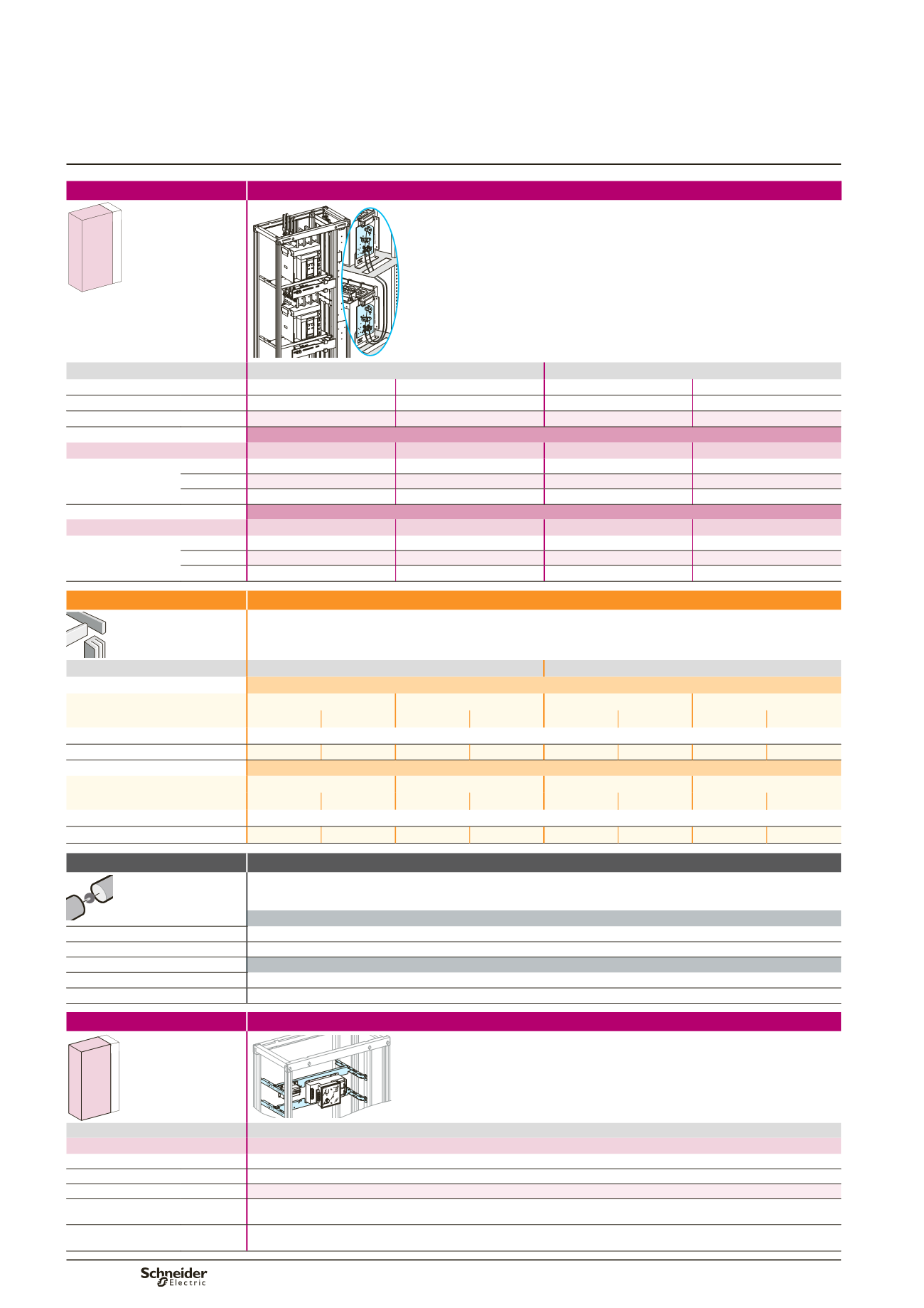
Masterpact NT06/16, front connection
S1 device different to S2 device
Source-changeover
Mounting
Front connection with cables
650 150
400
DD385441.eps
Devices
Fixed device
Withdrawable device
Number of devices per row
2
2
2
2
Number of vertical modules
26
26
28
28
Mounting plates
03484
03484
03483
03483
S1 device
NT12/16
NT06/10
NT12/16
NT06/10
Front plates
[No. of vertical
modules]
upstream
03804
[4]
03802
[2]
03804
[4]
03802
[2]
with cut-out
03692
[7]
03692
[7]
03691
[8]
03691
[8]
downstream
03803
[3]
03803
[3]
03803
[3]
03803
[3]
S2 device
NT06/10
NT12/16
NT06/10
NT12/16
Front plates
[No. of vertical
modules]
upstream
03803
[3]
03803
[3]
03803
[3]
03803
[3]
with cut-out
03692
[7]
03692
[7]
03691
[8]
03691
[8]
downstream
03802
[2]
03804
[4]
03802
[2]
03804
[4]
Connection
Devices
Fixed device
Withdrawable device
S1 device
NT06/10
NT12/16
NT06/10
NT12/16
3P
4P
3P
4P
3P
4P
3P
4P
Upstream connection
Front connections supplied with the device
Vertical connection adapters
33642
33643
33642
33643
33642
33643
33642
33643
S2 device
NT06/10
NT12/16
NT06/10
NT12/16
3P
4P
3P
4P
3P
4P
3P
4P
Downstream connection
Front connections supplied with the device
Vertical connection adapters
33642
33643
33642
33643
33642
33643
33642
33643
Mounting
Controller outside the device zone
650 150
400
MERLINGERIN
MERLINGERIN
DD383813.eps
Devices
UA or BA controller
Number of devices per row
1
Number of vertical modules
4
Mounting plates
03417
Front plates
[No. of vertical mod.]
with cut-out
03671
[4]
Characteristics
When a UA, BA or UA150 automatic controller is added together with an ACP mounting plate, the sources can be controlled
automatically according to a number of programmed operating modes.
Distribution
Linergy LGY, LGYE or BS busbars
Selection of Linergy LGY busbars:
see page B-14,
Linergy LGYE:
see page B-15,
Linergy BS:
see page B-16.
S1 device
Upstream connection
Front connections supplied with the device
Connection
must be made
S2 device
Downstream connection
Front connections supplied with the device
Connection
must be made
Functional system
Functional units