


 96 / 210

Linergydistributionsystems
Device feeders
Linergy FM
Quick device feeders
Description
b
b
Distribution over full rows of modular devices.
b
b
The distribution block is generally supplied by busbars in enclosures and cubicles.
b
b
Easy phase balancing.
b
b
Mix of devices and functions in the same row.
b
b
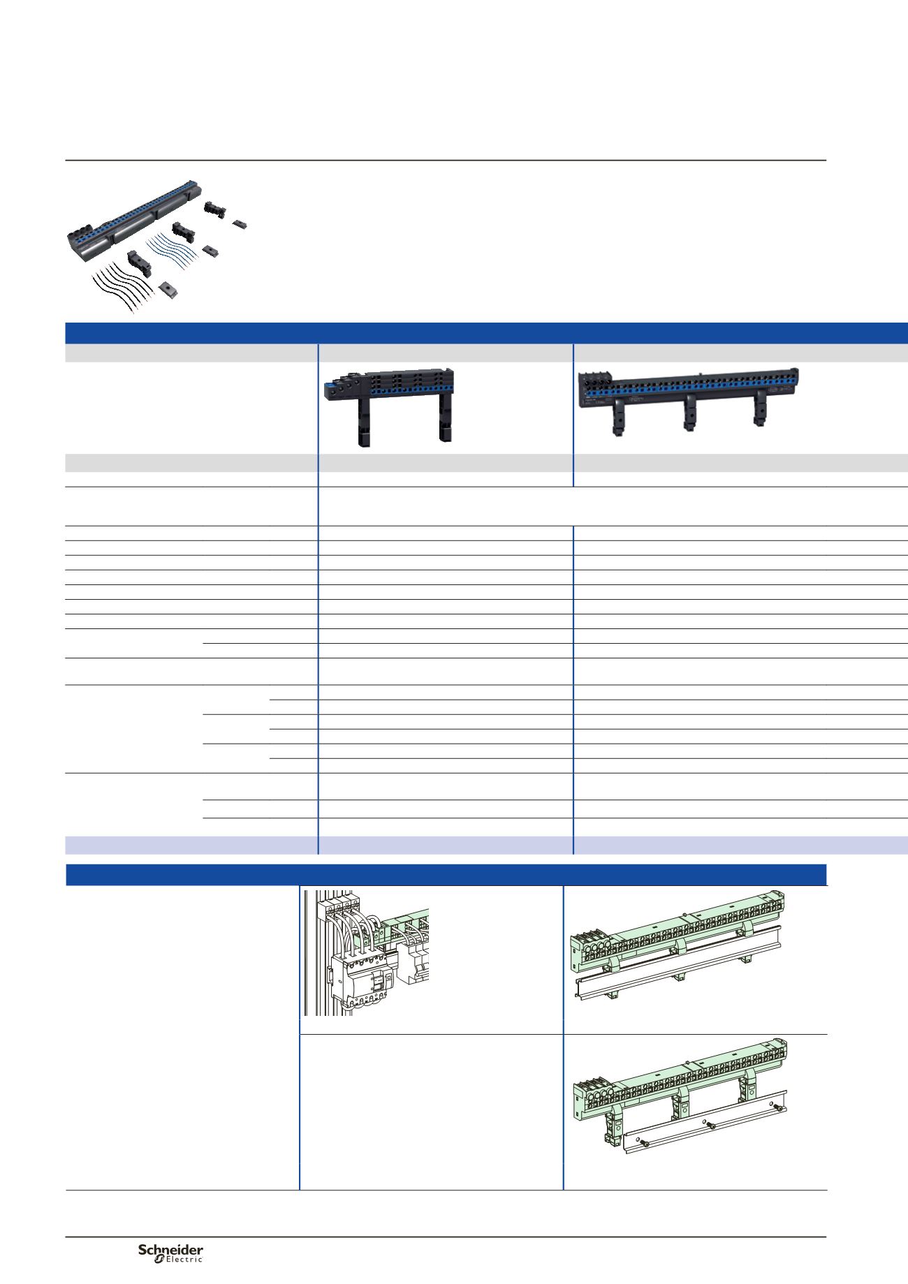
Installation
u
160 A: clipped onto the back of a modular rail or screwed onto a solid
or pre-slotted plate.
Installation
DD381664-LIN.eps
DB124195-LIN.eps
Clipped onto the back of a modular rail, or screw fixing. Clipped onto the back of a modular rail, or screw fixing.
DB124196-LIN.eps
Can be mounted in Pragma Evolution enclosures and
in Prisma Pack 160.
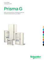
Distribution blocks
Number of poles
4P
4P
PB502496-31_r.eps
PB104501-52-r.eps
63 A
80 A
Rated peak withstand current
(Ipk)
15 kÂ
16 kÂ
Rated conditional short-circuit current
of an assembly
(Isc)
The cascading reinforced breaking capacity when combining circuit breakers is maintained. The worst-case
scenarios have been tested. The characteristics are exactly right for the connected devices. Circuit breakers
and switches still have their temperature derating curves, and their whole performance is maintained.
Insulation voltage
(Ui)
500 V AC
500 V AC
Rated voltage
(Ue)
440 V AC
440 V AC
Rated impulse withstand voltage
(Uimp) 6 kV
6 kV
Maximum current
(Imax) -
-
Thermal stress
(A².s)
2.400 x 10
6
2.400 x 10
6
Rated operational frequency
50/60 Hz
Degree of protection
IPxxB
IP20
Width
9 mm modules
24
48
18 mm modules
12
24
Supply at incoming terminals
Enclosed terminals for cables up to 25 mm
2
Enclosed terminals for flexible cables 6 to 25 mm
2
or rigid cables 10 to 35 mm
2
Downstream connection
capacity, cable to be used
without ferrules
Max. 4 mm
2
Phase 2
-
Neutral
4
-
Max. 6 mm
2
Phase 2
-
Neutral
4
-
Max. 10 mm
2
Phase -
18
Neutral
-
18
Accessories included
Pre-stripped copper
connections
10 x 4 mm
2
+ 6 x 6 mm
2
(W = 100 mm)
12 blue + 12 black
Protection cover
-
-
Fixings
-
-
Catalogue numbers
04008
04000
PB104505-50.eps
96