


 65 / 124

65
Technical advice
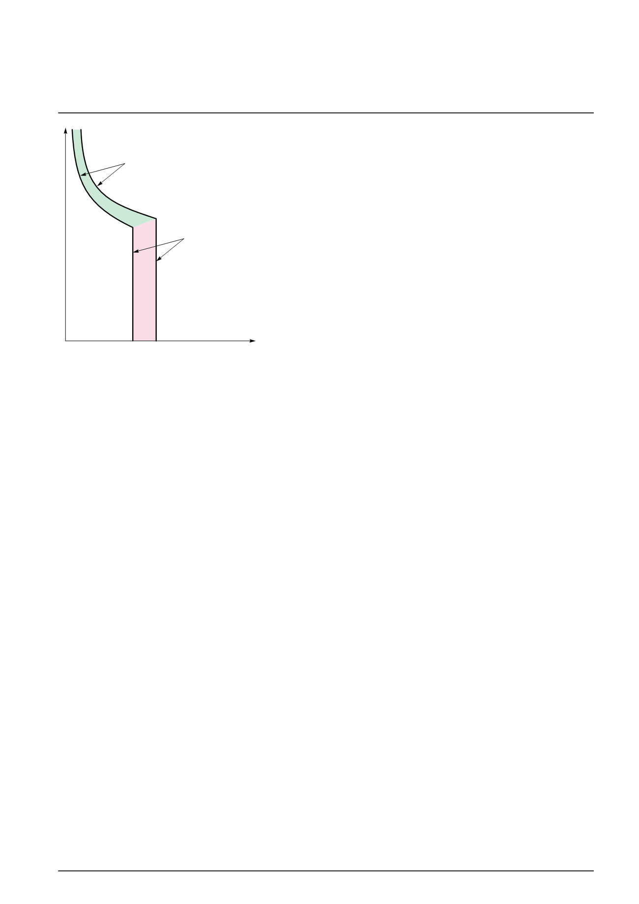
Tripping curves
In
t
Thermal tripping limits
Electromagnetic
tripping limits
min.
max.
DB124179
The following curves show the total fault current breaking time, depending on its
amperage. For example: based on the curve on page 3, an iC60 circuit breaker of
curve C, 20 A rating, will interrupt a current of 100 A (5 times the rated current In) in:
b
b
0.45 seconds at least
b
b
6 seconds at most.
The circuit breakers’ tripping curves consist of two parts:
b
b
tripping of overload protection (thermal tripping device): the higher the current, the
shorter the tripping time
b
b
tripping of short-circuit protection (magnetic tripping device): if the current exceeds
the threshold of this protection device, the breaking time is less than 10 milliseconds.
For short-circuit currents exceeding 20 times the rated current, the time-current
curves do not give a sufficiently precise representation. The breaking of high
short-circuit currents is characterized by the current limiting curves, in peak current
and in energy. The total breaking time can be estimated at 5 times the value of the
ratio (I
2
t)/(Î)
2
.
Verification of the discrimination between two circuit
breakers
By superimposing the curve of a circuit breaker on that of the circuit breaker installed
upstream, one can check whether this combination will be discriminating in cases of
overload (discrimination for all current values, up to the magnetic threshold of the
upstream circuit breaker). This verification is useful when one of the two circuit
breakers has adjustable thresholds; for fixed-threshold devices, this information is
provided directly by the discrimination tables.
To check discrimination on short circuit, the energy characteristics of the two devices
must be compared.