


 75 / 576

75
PB500368-54
Spacial S3D
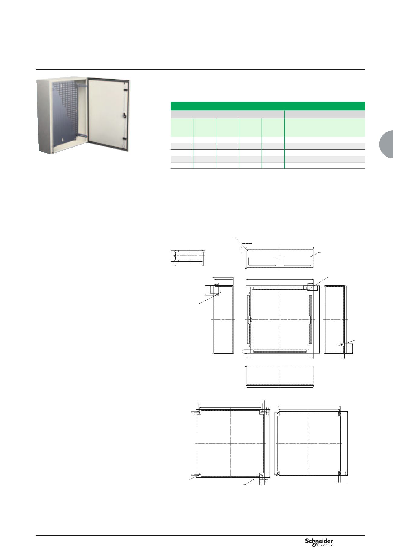
Steel wall-mounting enclosures
Additional information
Acceptable loads on the mounting plates,
bases and doors
Areas without cut-outs
For 800, 1000 and 1200-mm widths, 2 cable-gland plates:
see previous page.
Vertical cable guides from 400-mm height.
Horizontal cable guides from 800-mm width.
Download our DXF diagrams from our websites.
Spacial 3D wall-mounting enclosures
Acceptable loads (kg)
References
On plain
mounting
plates
On base On door
(1)
On
vertical
lug
On
horizontal
lug
60
135
50
350
190
NSYS3D3215
to
NSYS3D5320
90
135
50
350
190
NSYS3D5420
to
NSYS3D6425
135
135
50
350
190
NSYS3D6620
to
NSYS3D8630
150
135
50
350
190
NSYS3D10625
to
NSYS3D10830
180
135
50
350
190
NSYS3D101030D
to
NSYS3D141030D
(1) On a sheet door with a thickness of 20/10
e
mm: 60 kg of maximum acceptable load
(please consult us).
25
25
A-3
M6x17.5
C
C-23 50
120
90
70
55
70
55
90
120
50
M6x17.5
B
B-50
B-75
A-50
27
52
725
A
A-75
A-45
23
38
B-45
B-75
Ø10
55
38
23
55
M6x17.5
16
B-3
45
10
Flow hole
Cable gland plate
Right
P
P-23
Left
Door
Earthing stud
Earthing stud x 2
Bottom
Top
Back
Mounting plate (front view)
Backstud x 4
M8 x 25
Cable gland plate
hole (compulsory in
configured, optional
in specific)
DB300102EN-100