


 50 / 130

50
®
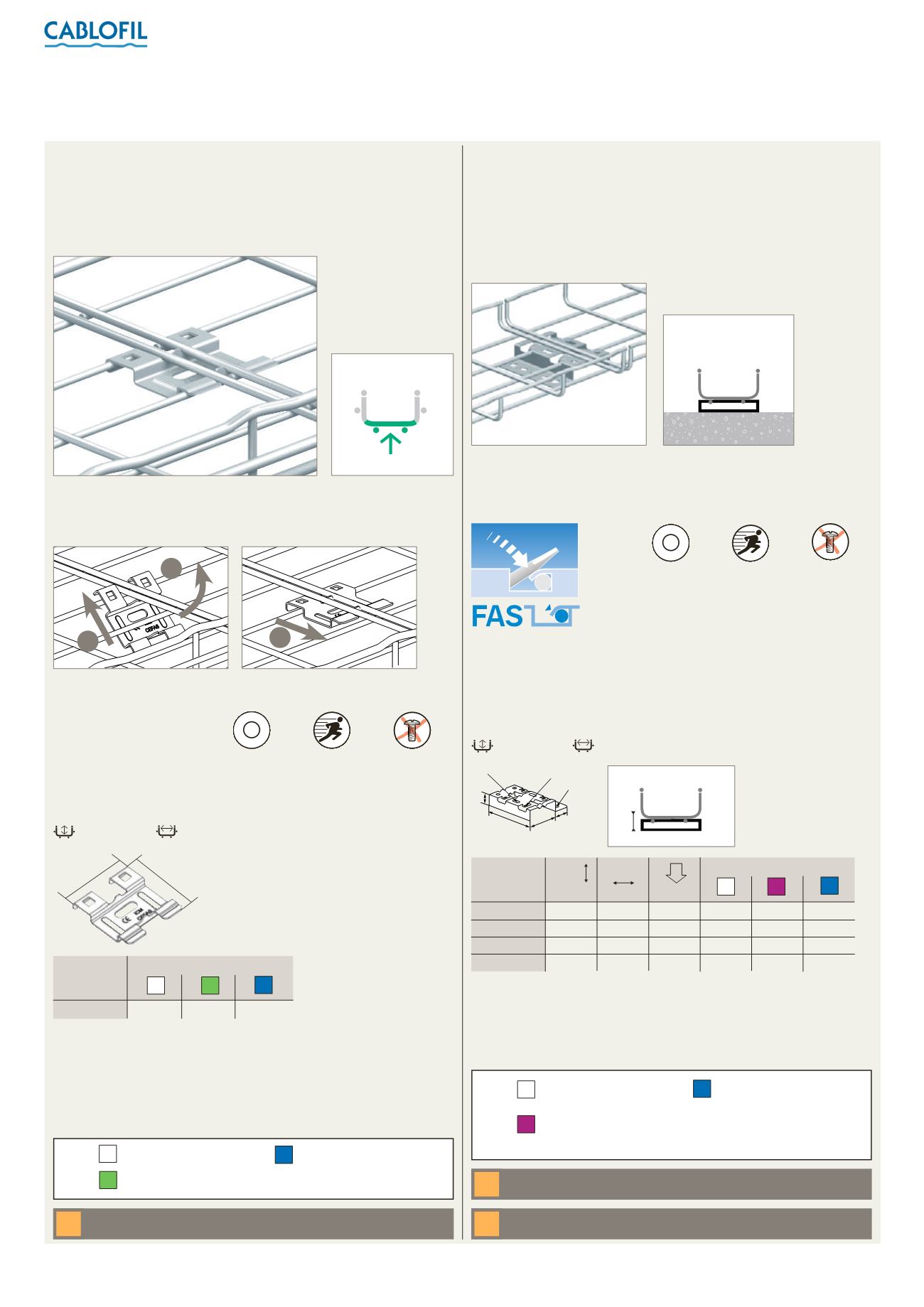
Installation
base couplers –
length to length
CEFAS - R15/25/35
n
Dimensions and weights
1
2
3
55
62
30
150 mm
100
600 mm
n
Assembly
All dimensions (mm) are nominal
Straight lengths : see p. 38-44
➔
CEFAS
0·03
0·04
0·34
Cat. Nos.
316L
Weight (kg)
DC
GS
CEFAS couplers are used as base couplers or in conjunction with
EDRN or AUTOCLIC as side rail couplers (p. 48). Can also be used as
a luminaire support. Supplied in packs of 50. No additional fasteners
or tools required
All weights are given in Kilograms (kg)
Please use Cat. No. when placing your order, see p. 18
CEFAS used as a base coupler between two lengths of steel wire cable
tray. No fasteners required
1. and 2. insert CEFAS into the
base of the tray as shown
3. slide into place to secure
No fasteners required
P
A
T
E
N
T
E
D
Patented
Fast
assembling
Fixing without
nuts and bolts
Pre-galvanised
Geomet
Stainless steel 316L
316L
For detailed information related
to inishes, refer to
p. 116-117
Key :
DC
GS
n
R15/25/35 – stand-off brackets
R15/25/35
30
105 mm
100
600 mm
Ø10
30
63
L
7 x 15
7 x 2·4
H
H
R15/25/35
P
A
T
E
N
T
E
D
Patented
Fast
assembling
Fixing without
nuts and bolts
Use to ix 100 mm to 600 mm wide steel wire cable tray in 30 mm to 150
mm depths directly onto the loor. For 200 mm and 300 mm wide tray,
use 2 x brackets per length. For 400 mm to 600 mm wide tray, use 3 x
brackets per length. Can also be used for wall mounting (see p. 63).
Incorporate slot and tab design for easy ixing. Supplied singly without
fasteners
Pre-galvanised
Continuous galvanisation
before manufacture
Stainless steel 316L
316L
For detailed information related
to inishes, refer to
p. 116-117
Key :
GS
Z+
Mount tray runs on the loor using R15/25/35 and fasteners (not supplied)
FA S T A S S EMBLING S Y S TEM
Slot base wires of the tray into the
stand-off bracket and bend tabs
with screwdriver to secure, as
shown in the FAS diagram above
Securing stand-off brackets to steel wire cable tray
All weights are given in Kilograms (kg)
Please use Cat. No. when placing your order, see p. 18
n
Assembly
n
Dimensions and weights
n
Installation
R15/100
15
98
100
0·14
0·09
0·09
R15/300
15
300
100
0·38
0·41
–
R25
25
98
100
0·13
0·12
–
R35
35
98
50
0·15
0·14
–
Cat. No.
daN
F
316L
Weight (kg)
GS
mm
H
Z+
mm
L
All dimensions (mm) are nominal
For wall mounting : see p. 63
➔
For floor mounting : see p. 79
➔
n
CEFAS – base couplers