


 40 / 130

40
®
INNOVATORS IN CABLE MANAGEMENT
�
1
2
3
straight lengths -
FCFA54 (FASCLIC AUTO)
technical information
n
Dimensions and weights
54 mm
50 mm
Ú
600 mm
3 m
n
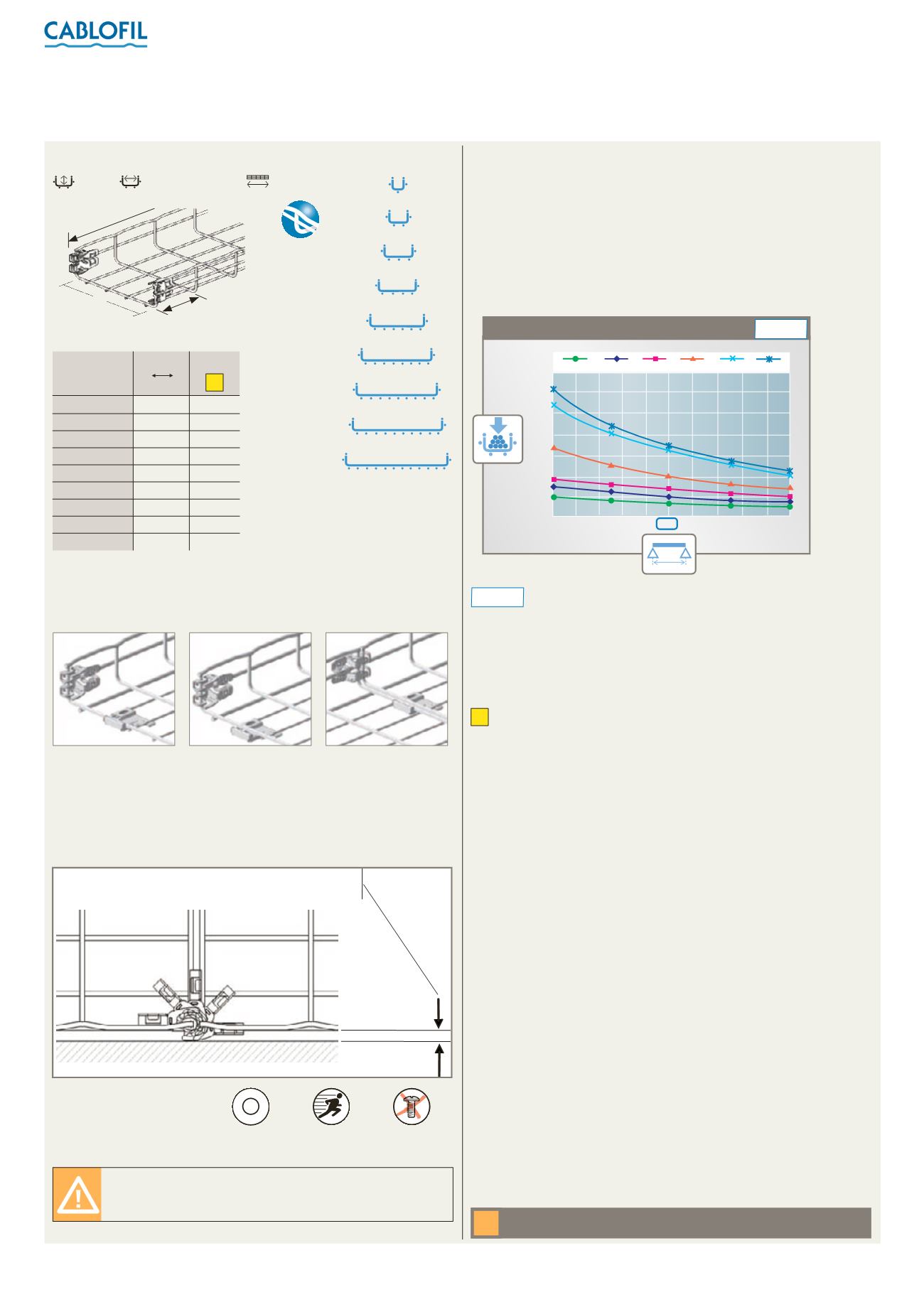
Loading graphs
FCFA54/50
FCFA54/100
FCFA54/150
FCFA54/200
FCFA54/300
FCFA54/400
FCFA54/450
FCFA54/500
FCFA54/600
From width 50 to 200 = minimum distance to the wall10 mm
From width 300 to 600 = minimum distance to the wall13 mm
n
Assembly
mm
L
kg/m mm
L
daN
F
1
mm
L
2
mm
H
kg/1 kg/100 daN.m
mm mm
L
W
FCFA54/50
50 1·97
FCFA54/100
100 2·40
FCFA54/150
150 3·20
FCFA54/200
200 4·15
FCFA54/300
300 6·23
FCFA54/400
400 9·26
FCFA54/450
450 9·89
FCFA54/500
500 9·89
FCFA54/600
600 10·53
Cat. Nos.
Weight
(kg)
EZ
B
o
r
d
S
é
c
u
r
i
t
é
B
r
e
v
e
t
é
Safety
edge
All weights are given in Kilograms (kg) and are for a 3 m straight length
Please use Cat. No. when placing your order, see p. 12
n
Finishes
Standard stocked finish :
EZ
Electrogalvanising after manufacture
For detailed information related to finishes, refer to
p. 116-117
Dividers : see p. 46
➔
Load tests carried out to IEC 61537 (safety factor 1·7 + joint
1
/
5
th
of the
way along the span). Permissable load should include all cable loads
and any other additional loads (eg: wind, snow)
NOTE:
For more information on loadings, see
p. 125
Unclip integral couplers from delivery position. Slide base plate
(if applicable) to accept secondary length. Clip coupler and base to
secure
For 300 - 600 mm wide tray, additional base plates are supplied to aid
connection (1 x for 300 mm, 2 x for 400 - 500 mm and 3 x for 600 mm
tray)
If a length of FCFA is cut, the coupler and base plate can be removed
and reattached
CF54/50
è
100 CF54/150 CF54/200 CF54/00 CF54/400
è
500 CF54/600
1500 1600 1700 1800 1900 2000 2100 2200 2300 2400 2500
kg/m
mm
EZ
P2000
140
120
100
80
60
40
20
0
= supports at 2 000 mm, see
p. 120
for more information
P2000
P
a
t
e
n
t
e
d
P
a
t
e
n
t
e
d
P
A
T
E
N
T
E
D
P
A
T
E
N
T
E
D
P
A
T
E
N
T
E
D
PATENTED
Patented
L
F
L
50
10
20
100
H
F
Fast
assembling
L
F
L
50
10
20
100
H
F
Fixing without
nuts and bolts
Sheared steel (particularly stainless steel) does
have relatively sharp edges and protective gloves
must be worn during handling
All dimensions (mm) are nominal
W
100
3000
The permissable load stated in this catalogue represents the load
that Cablofil steel wire cable tray is guaranteed to be able to bear. It
assumes loads are evenly spread and is given in daN/m. The standard
permits a deflection equivalent to 1/100th of the span. Legrand
imposes a stricter limit of 1/200th for both safety and aesthetic reasons.
For example, Legrand voluntarily restricts deflection to 10 mm for a
span of 2 m, whereas the standard would allow 20 mm.