
56
MR
medium rating busbar
determining the operating current of a busbar
In order to determine the correct busbar rating, the current must be
established using the following criteria :
•
type of load inputs – three phase or single-phase
•
type of circuit input – from one end, from both ends, central input, etc.
•
nominal input voltage
•
number, power and cos
j
of loads which are to be fed by the busbar
•
load diversity factor
•
load use nominal factor
•
assumed short circuit current at the input point
•
room temperature
•
type of busbar installation (edgeways, flat or vertical)
When using a three phase power supply, the operating current is
determined by the following formula :
Where :
I
b
operating current (A)
a
load diversity factor (.)
b
load use factor (.)
d
feed factor (.)
P
TOT
sum of the total active power of installed loads (W)
Ue
operating voltage (V)
cos
j
medium
average load power factor (.)
The ‘d’ input factor has a value of 1 when the busbar is fed from one
end only. The value is if fed from the centre or if it is fed from
each end
Once the operating current has been determined, choose the busbar
with a rated current immediately higher than the one calculated
All Zucchini products have been designed and tested for an average
room temperature of 40°C; should they be installed in rooms with
average daily temperatures different from 40°C, the rated current of the
busbar should be multiplied by a k1 factor that is greater than the unit
for temperatures lower than 40°C, and lower than the unit if the room
temperature is higher than 40°C
Finally, the following should be considered for the most appropriate
busbar choice :
where I
nt
represents the maximum current loaded by a busbar for an
indefinite time at the specified room temperature
I
b
= PTOT •
a
•
b
• d (A)
√
3 • Ue • cos
j
medium
I
nt
≥
I
b
I
nt
= k
1
• I
n
Voltage drop
If the length of the line is particularly long (>100m) it is necessary to check
the voltage drop (hereinafter specified as v.d.). If the installation is a three
phase system and the power factor is not lower than cosφ = 0.7 the v.d.
may be calculated with the coefficients of the voltage drop specified in the
technical data table.
Short circuit current
The short circuit current value I
CW
that can be supported by Zucchini busbar
trunking systems allows for both electrodynamic stress and thermal energy
dissipated during the fault
The busbars must be able to sustain the short circuit current for the entire
duration of the fault – i.e. for the time required for the protective device (circuit
breaker) to start operating, cutting off the metal continuity and extinguishing
the electric arc
Joule effect losses
Losses due to the Joule effect are essentially caused by the electrical
resistance of the busbar. Lost energy is transformed into heat and
contributes to the heating of the conduit
Three phase rating
Single phase rating
1
/
2
P = 3 • R
t
• I
b
2
• 10
-3
(W/m)
P = 2 • R
t
• I
b
2
• 10
-3
(W/m)
k
•
I
b
•
L
∆
v% = b
•
• 100
Vn
Defined :
I
b
= the current that supplies the busbar (A)
Vn
= the voltage power supply of the busbar (V)
L
= the length of the busbar (m)
∆
v%
= the voltage drop percentage
b
= the distribution factor of the current (.)
k
= corresponding voltage drop factor
a cos
j
(V/m/A) (see technical data table, p. 52-55)
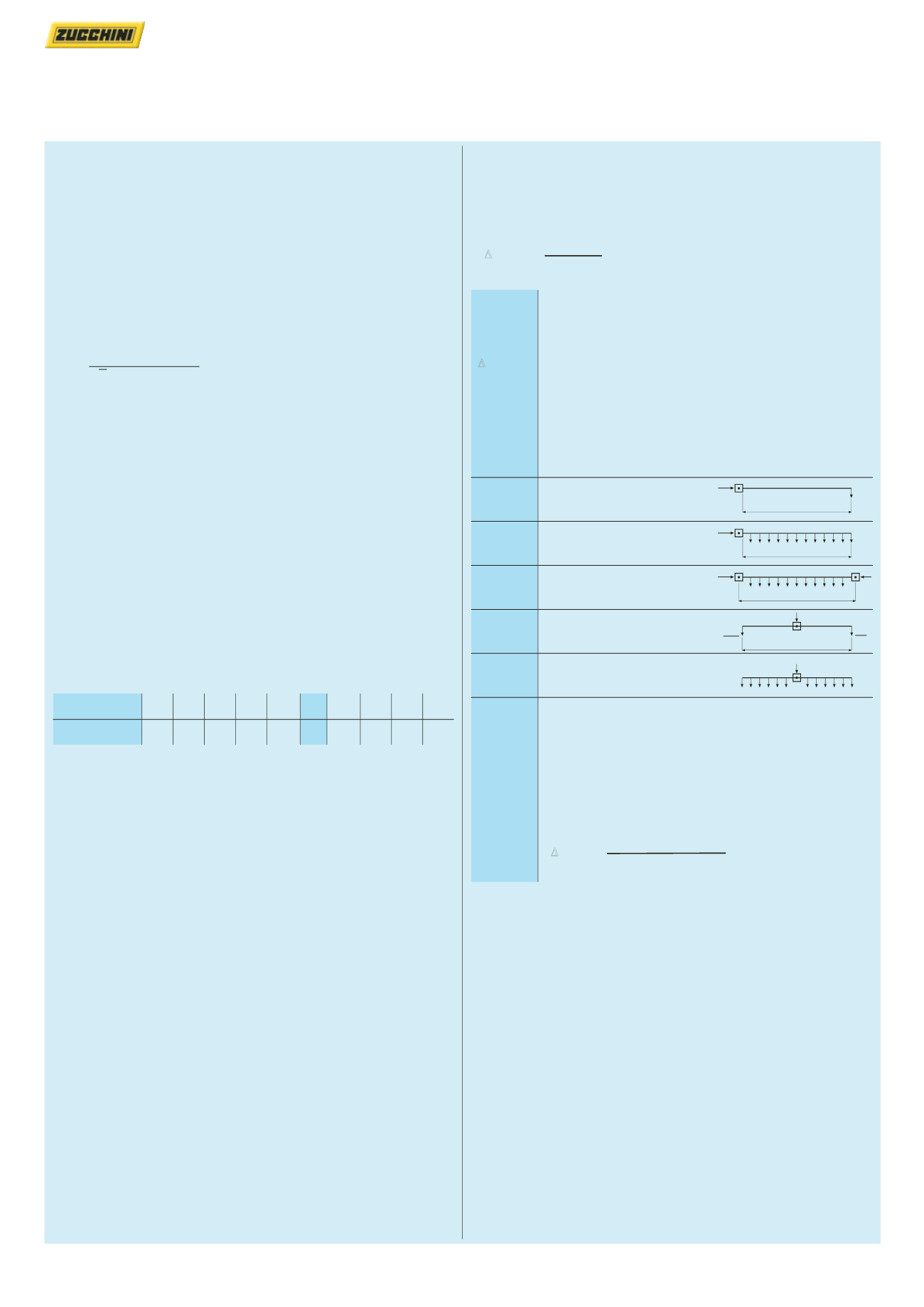
The current distribution factor “b” depends on how the
circuit is fed and on the distribution of the electric loads
along the busbar :
b = 2
Supplies at one end and load
at the end of the line
b = 1
Supplies at one end and with
load evenly distributed
b = 0·5
Supplies at both ends and with
load evenly distributed
b = 0·5
Central supply with loads
at both ends
b = 0·25
Central supply with load
distributed evenly
Example :
MR 400 A Al for riser mains feed
I
b
= 315 A operating current
b = 1
= supply from one end
k = 179
= see technical data table, p. 52-55
Cos
j
= 0·85
L
= 30 m line length
Vn
= 400 V operating voltage
I
b
L
I
b
I
b
L
I
b
I
b
L
I
b
L
I
b
2
I
b
2
179 • 10
-6
• 315 • 30
∆
v% = 1x
x100 = 0·42%
400
Room
15 20 25 30
35 40 45
50 55 60
temperature (°C)
k, thermal correction
1·15 1·12 1·08 1·05 1·025 1 0·975 0·95 0·93 0·89
factor (.)


