
50
MR
medium rating busbar
how to design the system
1
2
3
4
5
6
7
8
L1 PE L2 N L3
1
2
4
8
8
8
8
6
7
5
3
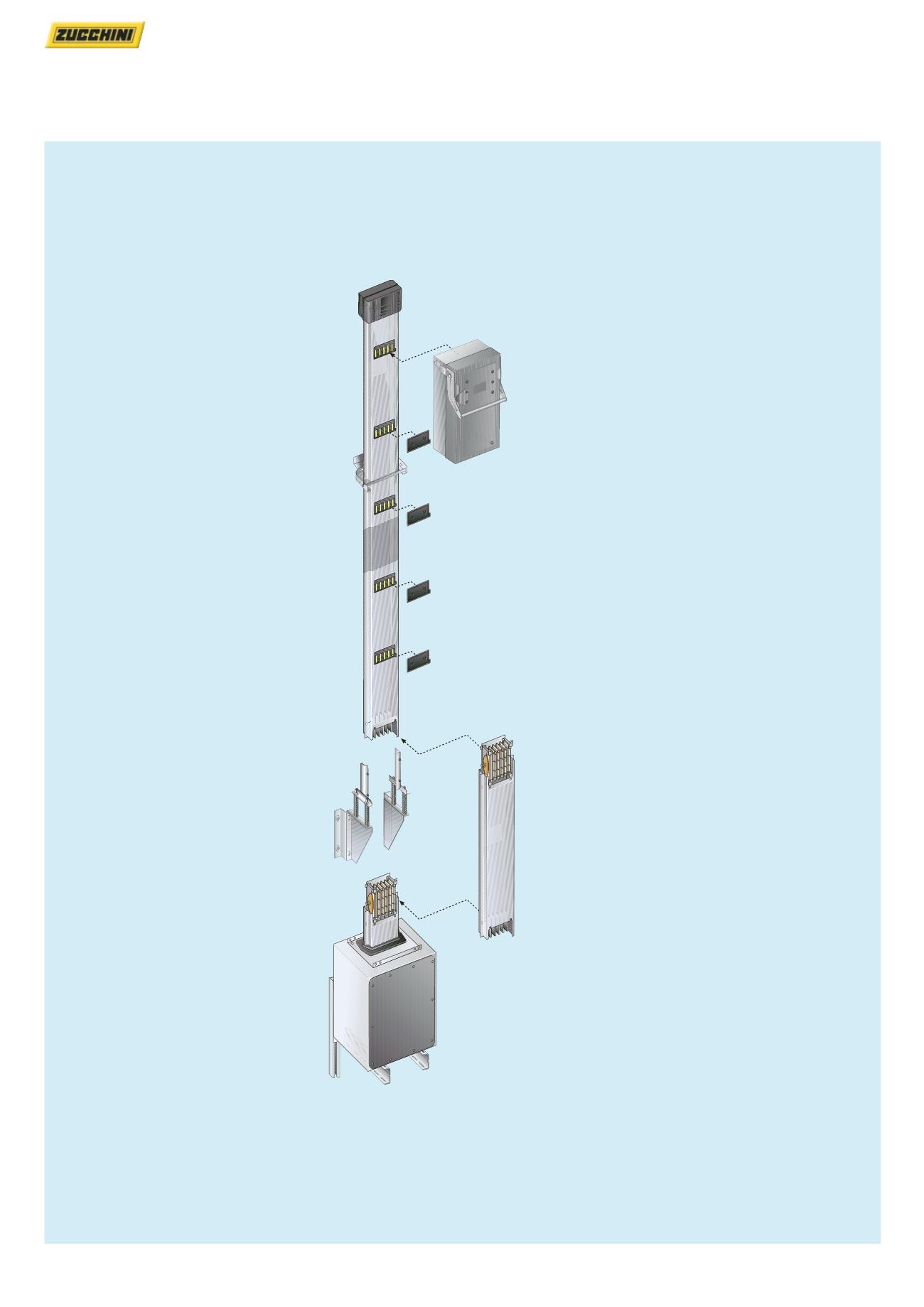
Use end feed unit LH – left hand
This gives the neutral bar
positioning on the right of
elements and the tap-off box with
cable entry at the base
Use the vertical hanger for
rising main as a function of the
run weight
For vertical lengths less than
4 metres fit on the base of the
busbar a vertical bracket (Cat. No.
50403711) for longer lengths use
vertical suspension hanger
(Cat. No. 50403712) every 300 kg
of rising main
Use standard suspension
brackets with spacer 40 mm
every 2 m of the rising main
Use straight lengths with plug
outlets on one side
Use the straight length with
fire barrier to maintain the fire
resistance of the floor
Please specify the position of the
internal fire barrier before placing
an order (see p. 140)
The tap-off box can be installed
on the joint between the
elements or on the outlets
At the end of the rising main use
the end cover IP 55
Before mounting the end cover
remove the monobloc prefitted on
the last element of rising main
Maintain the plug outlet covers
to guarantee the degree of
protection IP 55 to the run


