
13
LB PLUS
busbar trunking systems
technical data
n
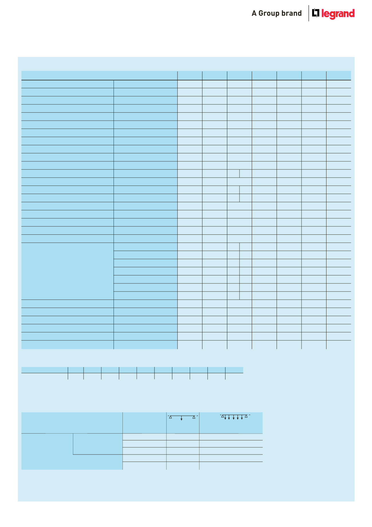
LB pLus – Type B
Type
252
254
256
258
404
408
634
Number of live conductors
2
4
6
8
4
8
4
Casing overall dimensions
LxH [mm]
35 x 77
35 x 77
35 x 77
35 x 77
35 x 77
35 x 77
35 x 77
Rated current
In [A]
25
25
25
25
40
40
63
Section of protective conductor
(1)
S
PE
[mm2]
195
195
195
195
195
195
195
Section of protective conductor
(1)
eq·Cu
S
PE
(=Cu) [mm2]
24
24
24
24
24
24
24
Operating voltage
Ue [V]
400
400
400
400
400
400
400
Insulation voltage
Ui [V]
690
690
690
690
690
690
690
Frequency
f [Hz]
5/6
5/6
5/6
5/6
5/6
5/6
5/6
Rated short-time current (0·1 s)
I
CW
[kArms]
2·5
2·5
2·5
2·5
3·2
3·2
3·2
Allowable peak current
Ipk [kA]
5
5
5
5
6·4
6·4
6·4
Thermal limit
I
2
t [A
2
s x 106]
0·625
0·625
0·625
0·625
1·024
1·024
1·024
20 °C phase resistance
R
20
[m
Ω
/m]
5·278
5·278
5·278 5·278
5·278
2·891
2·891
2·639
Phase resistance at thermal conditions
R
t
[m
Ω
/m]
6·798
6·798
6·798
6·798
3·793
3·793
3·399
Phase reactance (50Hz)
X [m
Ω
/m]
1·400
1·270
1·270 1·400
1·270
0·770
0·770
0·637
Phase impedance
Z [m
Ω
/m]
5·461
5·429
5·429 5·461
5·429
2·992
2·992
2·715
Resistance of the protective conductor
1
R
PE’
[m
Ω
/m]
0·434
0·434
0·434
0·434
0·434
0·434
0·434
Reactance of the protective conductor (50Hz) X
PE
[m
Ω
/m]
1·100
1·100
1·000
1·000
1·100
1·000
1·000
Resistance of the fault loop
R
o
[m
Ω
/m]
5·712
5·712
5·712
5·712
3·325
3·325
3·073
Reactance of the fault loop (50Hz)
X
o
[m
Ω
/m]
2·500
2·370
2·270
2·270
1·870
1·770
1·637
Impedance of the fault loop
Z
o
[m
Ω
/m]
6·235
6·184
6·147
6·147
3·814
3·766
3·482
∆
V 10
-3
cos
j
= 0·70 [V/m/A]
4·07
3·99
3·99 4·07
3·99
2·23
2·23
1·99
∆
V 10
-3
cos
j
= 0·75 [V/m/A]
4·23
4·16
4·16 4·23
4·16
2·32
2·32
2·08
∆
V 10
-3
cos
j
= 0·80 [V/m/A]
4·38
4·32
4·32 4·38
4·32
2·40
2·40
2·16
Voltage drop with distributed load
∆
V 10
-3
cos
j
= 0·85 [V/m/A]
4·52
4·46
4·46 4·52
4·46
2·48
2·48
2·23
∆
V 10
-3
cos
j
= 0·90 [V/m/A]
4·64
4·59
4·59 4·64
4·59
2·54
2·54
2·30
∆
V 10
-3
cos
j
= 0·95 [V/m/A]
4·72
4·69
4·69 4·72
4·69
2·59
2·59
2·34
∆
V 10
-3
cos
j
= 1·00 [V/m/A]
4·57
4·57
4·57 4·57
4·57
2·50
2·50
2·29
Weight
p [kg/m]
1·80
1·83
2·02
2·02
1·98
2·33
2·33
Fire load
[kWh/m]
1·1
1·1
2·1
2·1
1·1
2·1
2·1
Protection index
IP
55
55
55
55
55
55
55
Degree of impact-resistance
IK
7
7
7
7
7
7
7
Joule effect losses at rated current
P [W/m]
12·7
12·7
12·7
12·7
18·2
18·2
40·5
Ambient temperature min·/MAX·
t [°C]
-5/+50
-5/+50
-5/+50
-5/+50
-5/+50
-5/+50
-5/+50
1 : metal casing
2 : Distributed load total weight
Temperature rating schedule according to the room temperature
Room temperature [°C] 15
20
25
30
35
40
45
50
55
60
K1 Factor
1·15
1·12
1·08
1·05
1·025
1
0·975 0·95
0·93
0·89
Multiplier coefficient of rated current for room temperature values different from 40° C
Mechanical loads permitted table
The table shows the maximum weights (kg) that can be supported,
both for concentrated, and distributed loads
1·5
40
50 kg/m
(75 kg)
2
LB pLus – TYpE A
2·0
30
30 kg/m
(60 kg)
2
LB pLus – TYpE B
3·0
20
13 kg/m
(39 kg)
2
5·0
13
5 kg/m
(25 kg)
2
7·0
7
2 kg/m
(14 kg)
2
Distance between
Concentrated
Distributed
suspension brackets
load
load
LB PLUS -TYPE A
LB PLUS - TYPE B
Distancebetween
suspensionbrackets
**Distributed load totalweight
1.5 m
2 m
3 m
5 m
7 m
40 kg
30 kg
20 kg
13 kg
7 kg
50 kg/m
30 kg/m
13 kg/m
5 kg/m
2 kg/m
(75 kg)**
(60 kg)**
(39 kg)**
(25 kg)**
(14 kg)**
Distributed
load
Concentrated
load
LB PLUS -TYPE A
LB PLUS - TYPE B
Distancebetween
suspensionbrackets
**Distributed load totalweight
1.5 m
2 m
3 m
5 m
7 m
40 kg
30 kg
20 kg
13 kg
7 kg
50 kg/m
30 kg/m
13 kg/m
5 kg/m
2 kg/m
(75 kg)**
(60 kg)**
(39 kg)**
(25 kg)**
(14 kg)**
Distributed
load
Concentrated
load


