


 172 / 244

Synergy
®
white
control switches
164
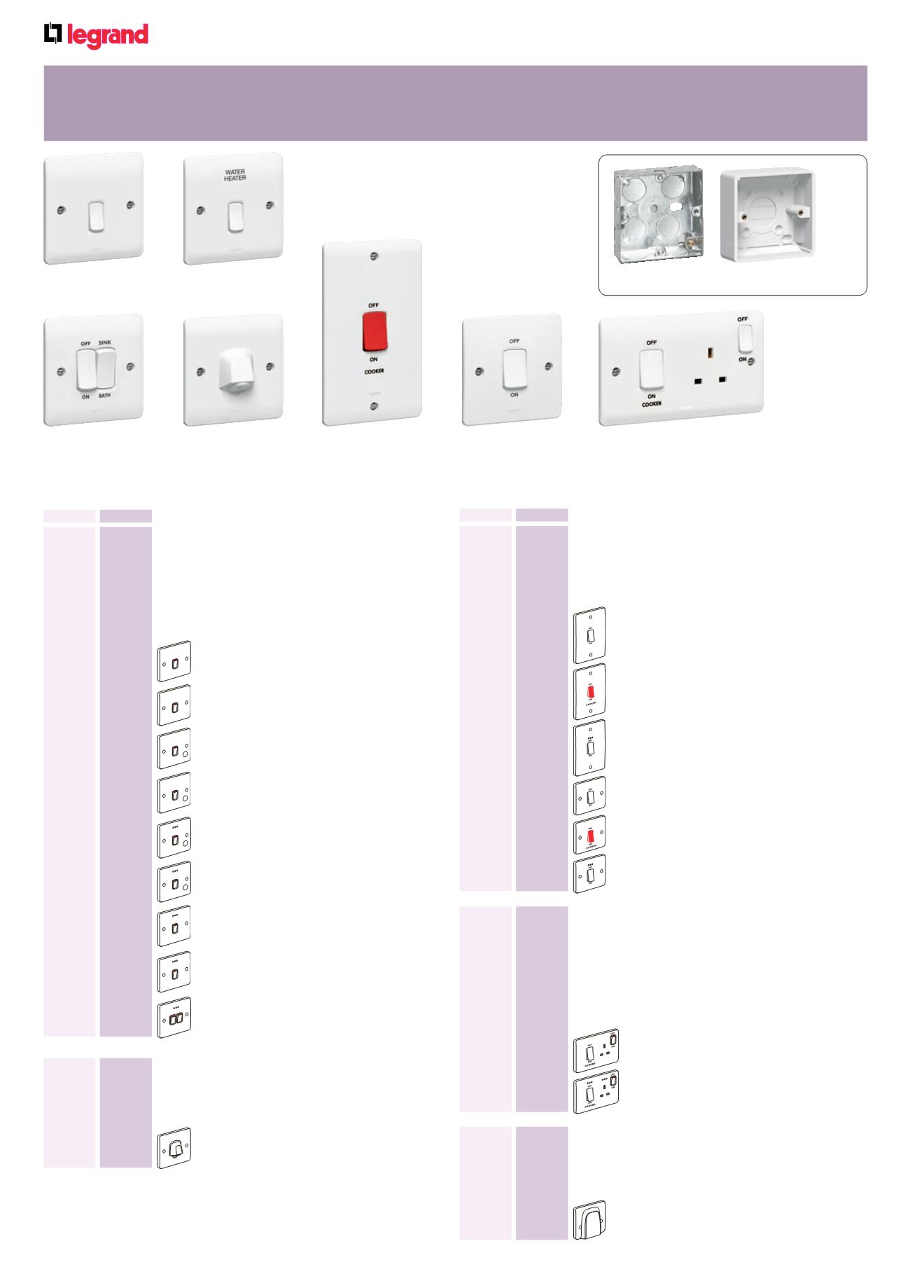
Cable outlet 20 A - 250 V
±
Conforms to BS 5733 : 1995
Flush mounting back box : min. 25 mm deep
Nominal plate dimensions : 86 x 86 mm
10
7300 19
20 A – with terminal block and outlet gland
Front plates : white thermoset
Terminal screws captive and backed off ready for cabling
Supplied with faceplate screw caps
Pack
Cat. Nos.
Double pole switches 20 A - 250 V
±
1
Conform to BS EN 60669-1 : 2000
Options available as standard with red ‘power on’ LED
indicator
LED ‘power on’ upgrade pack also available
Use cord outlet accessory box Cat. No. 7300 53 for
flush to wall external cord connection, (see p.166)
Flush mounting back box : min. 25 mm deep
Nominal plate dimensions : 86 x 86 mm
10
7300 10
20 A DP
10
7301 10
20 A DP marked “WATER HEATER”
10
7300 14
20 A DP with cord outlet
10
7301 14
20 A DP with cord outlet
marked “WATER HEATER”
10
7300 16
20 A DP with cord outlet +
red LED power indicator
10
7301 16
20 A DP with cord outlet
marked “WATER HEATER” +
red LED power indicator
10
7300 12
20 A DP + red LED power indicator
10
7301 12
20 A DP marked “WATER HEATER” +
red LED power indicator
10
7300 18
20 A sink/bath dual switch +
red LED power indicator
7300 19
Cable outlet 45 A - 250 V
±
Conforms to BS 5733 : 1995
2 piece design for safety
Flush mounting back box : min. 48 mm deep
Nominal plate dimensions : 86 x 86 mm
5
7300 26
45 A – with terminal block
WATER
HEATER
WATER
HEATER
WATER
HEATER
WATER
HEATER
Pack
Cat. Nos.
Double pole switches 45 A - 250 V
±
Conform to BS EN 60669-1 : 2000
Options available as standard with red ‘power on’ LED
indicator
LED ‘power on’ upgrade pack also available
Flush mounting back box : min. 48 mm deep
Nominal plate dimensions : 2 gang - 146 x 86 mm
1 gang - 86 x 86 mm
5
7300 20
45 A DP
5
7301 20
45 A DP with red rocker marked “COOKER”
5
7300 21
45 A DP + red LED power indicator
10
7300 22
45 A DP
10
7301 22
45 A DP with red rocker marked “COOKER”
10
7300 23
45 A DP + red LED power indicator
7300 10
7301 10
7300 18
7300 29
7300 23
7301 20
Cooker control units 45 A - 250 V
±
Conform to BS 4177 : 1992
Options available as standard with red ‘power on’ LED
indicator
LED ‘power on’ upgrade pack also available
45 A - 250 V
±
double pole switch with
13 A - 250 V
±
double pole switched socket outlet
Flush mounting back box : min. 48 mm deep
Nominal plate dimensions : 86 x 146 mm
5
7300 28
DP with DP switched socket
5
7300 29
DP with DP switched socket +
red LED power indicator
OFF SINK
ON BATH
1 : Range of engraving available on most products, see table on p.169
Flush and surface mounting back boxes p. 167 For red power indicator LED pack, see p.166