


 167 / 244

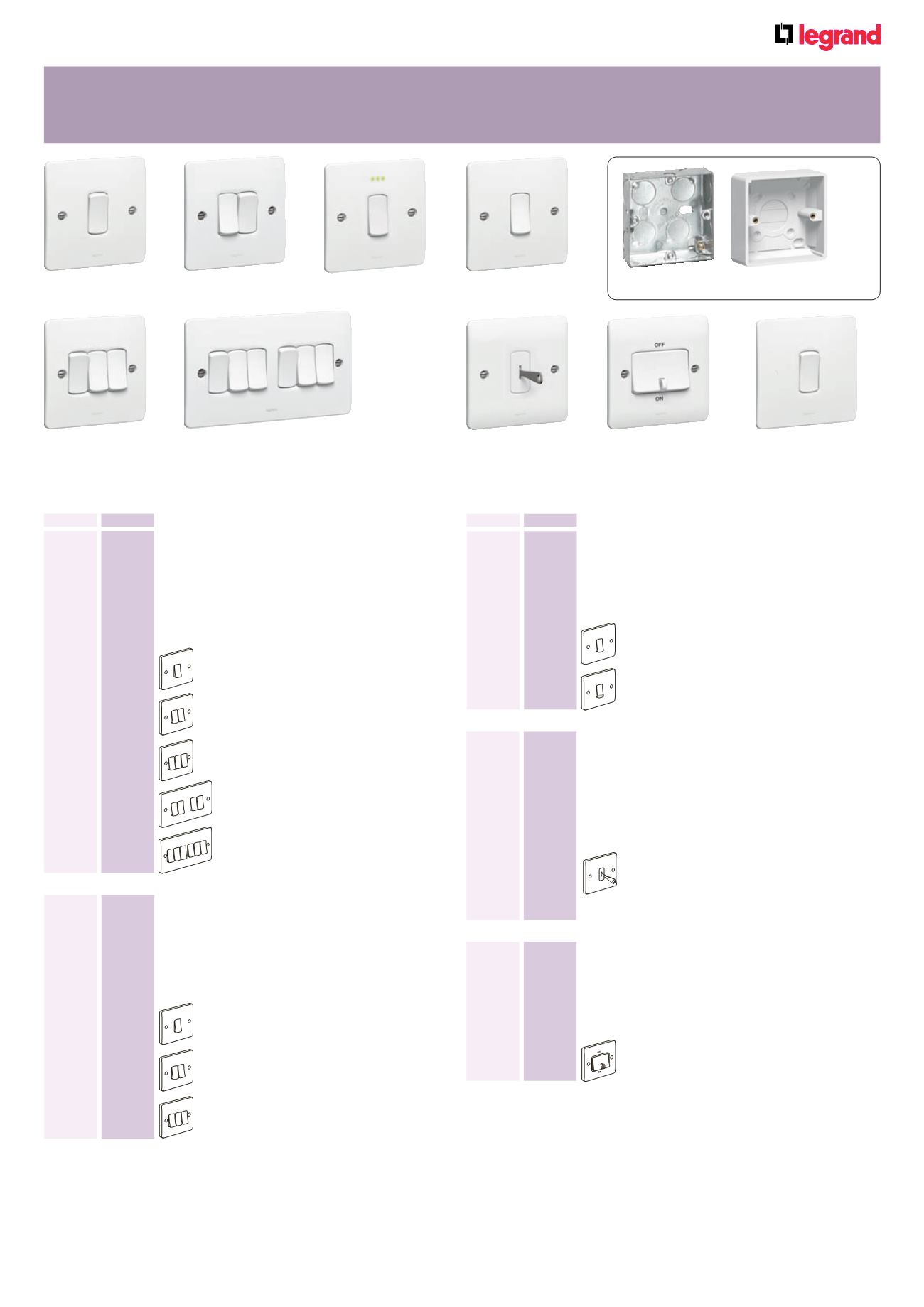
Front plates : white thermoset
Terminal screws captive and backed off ready for cabling
Supplied with optional faceplate screw caps
Pack
Cat. Nos.
Single pole plate switches
10 AX - 250 V
±
Conform to BS EN 60669-1 : 2000
Optional Red LED ‘power on’ indicator and green
LED ‘locator’ upgrade packs available
Flush mounting back box : min. 16 mm deep
Nominal plate dimensions :
1, 2 and 3 gang - 86 x 86 mm
4 and 6 gang - 86 x 146 mm
10
7300 00
1 gang – 1 way
10
7300 01
1 gang – 2 way
10
7300 05
1 gang – intermediate
10
7300 02
2 gang – 2 way
10
7300 03
3 gang – 2 way
5
7300 04
4 gang – 2 way
5
7300 06
6 gang – 2 way
Synergy
®
white
switches
7300 08
7300 07
7300 06
7300 02
7300 00 + optional locator
LED (Cat. No. 7301 58)
7300 09 + optional
screw caps (included)
7300 09
7301 33
Single pole key switch
10 AX - 250 V
±
Conforms to BS EN 60669-1 : 2000
Optional Red LED ‘power on’ indicator and green
LED ‘locator’ upgrade packs available
Key supplied
Flush mounting back box : min. 16 mm deep
Nominal plate dimensions : 86 x 86 mm
10
7300 08
1 gang – 2 way
5
0811 77
Spare key for above
7300 00
Single pole plate switches
20 AX - 250 V
±
Conform to BS EN 60669-1 : 2000
Optional Red LED ‘power on’ indicator and green
LED ‘locator’ upgrade packs available
Flush mounting back box : min. 25 mm deep
Nominal plate dimensions : 86 x 86 mm
10
7301 30
1 gang – 1 way
10
7301 31
1 gang – 2 way
10
7301 32
2 gang – 2 way
10
7301 33
3 gang – 2 way
For green locator LED pack or red power indicator LED pack, see p.166 For green locator LED pack or red power indicator LED pack, see p.1663 pole fan switch 10 A - 250 V
±
Conforms to BS EN 60669-1 : 2000
With integrated padlockable safety block
in OFF position
Flush mounting back box : min. 25 mm deep
Nominal plate dimensions : 86 x 86 mm
10
7300 09
3 pole fan switch
Pack
Cat. Nos.
Single pole push switches
10 A - 250 V
±
Conform to BS EN 60669-1 : 2000
Optional Red LED ‘power on’ indicator and green
LED ‘locator’ upgrade packs available
Flush mounting back box : min. 16 mm deep
Nominal plate dimensions : 86 x 86 mm
5
7300 07
1 gang – 2 way push switch
5
7300 11
1 gang – 2 way push switch marked “PRESS”
Flush and surface mounting back boxes p. 167159