


 46 / 108

46
raised floor systems
customer services +44 (0)1745 532343
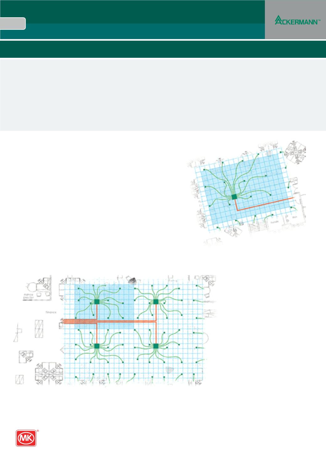
Spider
1
Position outlets in a grid pattern
l
High density applications: Every 3rd floor tile
l
Medium density applications: Every 4th floor tile
l
Low density applications: Every 5th floor tile
2
Centrally position the Spider hub to feed 12 outlets
l
High density applications require 1 hub per 38m
2
l
Medium density applications require 1 hub per 70m
2
l
Low density applications require 1 hub per 108m
2
3
Estimate quantity of umbillical reels
l
Outlet on 3 tile grid = approx 35m per hub
l
Outlet on 4 tile grid = approx 50m per hub
l
Outlet on 5 tile grid = approx 65m per hub
4
Continue grid pattern across the rest of the floor
It is important to plan the layout so that the spider hub can be easily accessed simply by lifting a floor tile, situated above each hub.
Individual power supplies can be isolated without lifting the floor tile by accessing breakers through a hatchway in the floor tile.
Spider – The Planning
Spider can be easily applied to many situations, providing significant benefits to both the planner and end user.
l
Practical and flexible system – final desk layout prior to planning the Spider installation is not necessary
l
Service Outlets – provided at the required density
l
Workstations – easily located in a variety of configurations to suit your needs
l
Simple to plan – designed around a basic grid principle (utilising typical 600x600mm floor tiles)