


 16 / 99

15
Echo™
Technical
technical hotline +44 (0)1268 563720
wireless
|
wiring devices
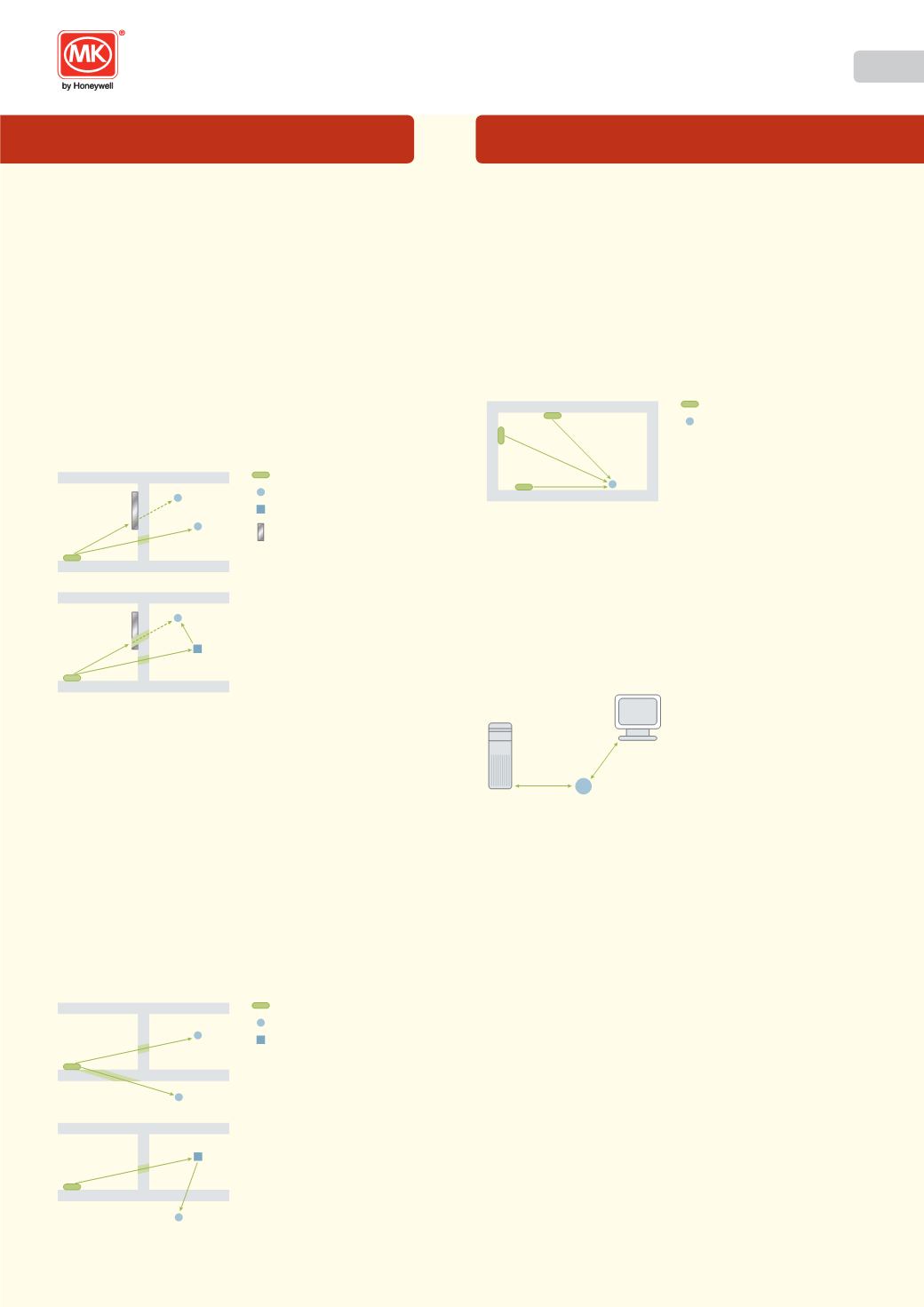
3. SCREENING
Objects made of metal, such as wall reinforcements, the metal foil often
used in certain forms of insulation, or metallised heat protected glass,
reflect electromagnetic waves and thus create what is known as a radio
shadow and thereby a reduction in transmission distance.
The main factors decreasing coverage include:
l
A Transmitter mounted on metal surfaces (typically 30% loss of range).
l
Transmitters with metal frontplates (typically 60% loss of range).
l
Hollow lightweight walls filled with insulating wool on metal foil.
l
Inserted ceilings with panels made of metal or carbon fibre.
l
Lead glass or glass with metallised coating, steel furniture.
Please note: Fire-safety walls, elevator shafts, staircases and supply
areas should be considered as screening.
WALLS
WALLS
Transmitter
Receiver
Repeater
Metal
sheet
✓
✗
✓
✗
Simple example of a possible screening problem.
Depending on the material used to build the walls and assuming the
distance between the transmitters and receivers are within specification,
the illustrations above show a typical screening problem.
For the best range performance a minimum distance of 10mm to
20mm should be allowed from the whole length of the antenna to any
conductive objects, which effectively means the area surrounding the
Switch Receiver module.
Avoid screening by repositioning the Transmitter and / or Switch Receiver
away from the screening objects (radio shadow), or if this is not possible,
by using a Repeater.
4. PENETRATION ANGLE
The angle at which the transmitted signal hits the wall is very important.
The effective wall thickness – and with it the signal attenuation – varies
according to this angle. Signals should be transmitted as directly as
possible through the wall. Wall niches should be avoided.
WALLS
WALLS
Transmitter
Receiver
Repeater
✓
✗
✓
Avoid an unfavourable penetration angle by repositioning the Transmitter
and / or Receiver, or by using a Repeater.
Do not position a Switch Receiver behind a Transmitter. In this
position the signal strength is greatly reduced, even if there is no
wall in-between.
5. ANTENNA INSTALLATION
S
witch Receivers should not be installed on the same wall as the
Transmitter. When positioned near a wall, the radio waves are
likely to be subject to interfering dispersions or reflections.
WALLS
Transmitter
Receiver
✓
✓
✗
In a similar manner to the comment in the previous section, positioning
transmitters and receivers along the same wall will mean the signal
strength is greatly reduced.
6. DISTANCE BETWEEN SWITCH RECEIVERS AND A SOURCE OF
INTERFERENCE
The distance between Switch Receivers and other transmitters (e.g.
GSM / DECT / wireless LAN) or high-frequency sources of interference
(computers, audio and video equipment) should be at least 500mm.
However, Echo Transmitters can be installed next to any other high-
frequency transmitter without a problem.
Receiver
>50cm
>50cm
PC
7. USE OF REPEATERS
In the case of poor reception, it may be helpful to use a Repeater.
The Echo Repeater (K5414R) does not require any configuration (e.g.
programming) and will become operational simply by connecting it to
the mains supply. The new 10AX Switch Receiver/Repeater (K5420R)
is also a repeater when not programmed with any switches. The
various possibilities of use are shown by the illustrations in sections
3. SCREENING and 4. PENETRATION ANGLE.
A Repeater has similar requirements in being positioned as a Switch
Receiver, i.e. it too has an antenna and needs to receive the signal from
the Transmitter and be within range of the Switch Receiver with which it is
intended to communicate.
While planning, it may be worth considering retrofitting the system with a
Repeater.
Only one repeater is intended for use in any single installation. Using
more than one repeater is counterproductive (higher cost, cross-signal
interference, etc).
Echo™ is a registered trademark of Novar ED&S Limited