


 401 / 582

BETA Switching
Timers
5
TT3 18 timers for industrial applications
9/23
Siemens ET B1 · 10/2008
9
5
TT3 185 multifunctional timers
Setting aids
The period of the flashing of the green LED 1 when set for a timing
interval is 1 s
±
4%,
which can therefore be used as a setting aid.
This is particularly useful in the lower time setting range and for
long delay times because the multiplication factors between the
individual time ranges are exact.
Example:
Delay time to be set: 40 min.
Using the fine setting, this delay time can be set within the setting
range 3 ... 300 min. However, in this case it takes a long time to
check the time and requires several operational sequences in
realtime. To speed up the setting process, the setting range will
be switched to 0.03 ... 3 min. In this case, the required value
corresponds to a delay time 0.4 min (= 24 s). The timing interval
is triggered and the potentiometer is set to 24 flashing periods of
the yellow LED 2. The device is then set back to the setting
range 3 ... 300 min and the setting process is completed.
Time operation interruption/time addition
For the functions AV, EW, IE, BI, the timing interval can be
interrupted at any time by activating B1 (+) and by removing the
control voltage continued again (time addition).
Control input B1
The functions RV, IF, AW, AV/RV can be controlled using the
control input B1 (+) with potential against terminal A2. The
auxiliary voltage of terminal A1 can be used for this purpose, as
well as any other voltage within the range 12 ... 240 V AC/DC.
The operation of parallel loads (e.g. contactors) from B1 (+) to
A2 is also permissible.
If voltage is simultaneously applied to the control input B1 (+)
and A1 for the IF function, this triggers an output pulse with the
set time interval t
1
.
15-18
15-16
t
t
t
t
t
t
t
t
t
t
t
t
t
t
t
t
t
t
15-18
15-16
15-18
15-16
15-18
15-16
15-18
15-16
A1-A2
B1-A2
15-18
15-16
15-18
15-16
15-18
15-16
t
0,5
s
1
2
3
4
5
6
7
8
I2_10908b
A1-A2
B1-A2
c
St
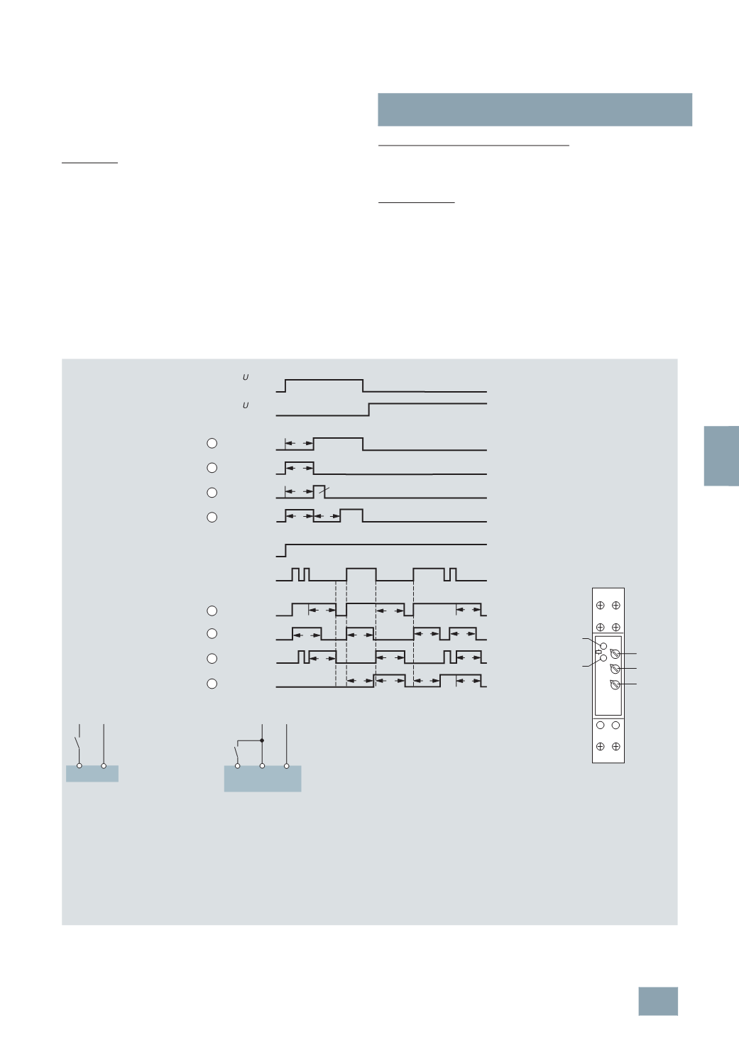
Contact
Position
Function
switch
Response delay
Pulse generator, delayed
Passing make contact
function
Flashing relay,
starting with impulse
OFF-delay
Pulse shape
Passing break contact
function
Response delay
OFF-delay
Control S1
Control S2
AV
EW
IE
BI
RV
IF
AW
AV/RV
S2
N
A2
A1
B1(+)
L +
S1
N
A2
A1
L +
Possible time setting ranges
t
➀
AV
= Response delay
➁
EW = Passing make contact function
➂
IE = Pulse generator, delayed
➃
BI
= Flashing relay, starting
with impulse
➄
RV = Off-delay
➅
IF = Pulse shape
➆
AW = Passing break contact function
➇
AV/RV= Response/off delay
0.02 ...
1
s
0.06 ...
6
s
0.3 ...
30
s
0.03 ...
3
min
0.3 ...
30
min
3
...
300
min
0.3 ...
30
h
3
...
300
h
Control S1
Control S2
Contact S1
For the functions: response delay,
passing make contact function,
pulse generator delayed,
clock generator – (start with pulse) –
the timing interval is triggered by
closing the switching contact S1.
Control contact S2
The functions: off-delay,
pulse shape, passing break contact
function,
response and off-delay are triggered
by continuous power supply over
the control contact S2 between A1
and B1 (+).
Front view
LED 1 green:status display
LED 2 yellow:switching
position indication
E1: Setting range adjuster
Z: Fine adjuster for
setting ranges
E2: Function settings for
timing intervals
A1 15
B1
16 18
A2
(
+)
E1
Z
E2
I2_11970
LED 1 green
LED 2 yellow
Operator interfaces
LED 1 Status display
LED 2 Switching position indication
E1 Setting range adjuster
Z Fine adjuster for setting ranges
E2 Function settings for timing intervals
Device displays
LED 1 Lights up if operational voltage
is applied (green)
LED 2 Indicates the timing interval and
state of the equalizing relay (yellow)
•
Continuous light
-
Off output relay not activated,
no timing interval
-
On output relay not activated,
no timing interval
•
Flashing light
-
Short on, long off
Output relay not activated, timing interval
-
Short on, long off
Output relay activated, timing interval
© Siemens AG 2008