


 120 / 582

BETA Protecting
Residual Current Protective Devices
SIQUENCE 5SM3, 5SU1 universal
current-sensitive type B
2/12
Siemens ET B1 · 10/2008
2
*
You can order this quantity or a multiple thereof.
■
More information
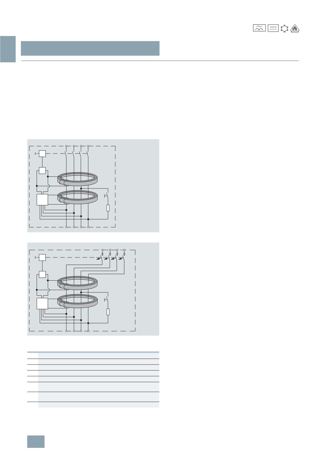
Device setup
Universal current-sensitive protective devices are based on a
pulse-current-sensitive circuit-protection device with tripping
independent of supply voltage, supplemented with an auxiliary
unit for the detection of smooth DC residual currents.
The diagrams below show the basic design.
The summation current transformer W1 monitors the electrical
system for AC and pulse current-type residual currents. The
summation current transformer W2 detects the smooth DC
residual currents and, in the event of a fault, relays the tripping
command through electronic unit E to release A, which uses the
mechanics to disconnect the circuit.
Design of RCCBs
Design of RCBOs
Method of operation
The universal current-sensitive residual current protective
devices work independent of the supply voltage compliant with
current requirements in Germany for type A according to
DIN VDE 0664-100.
A voltage supply is required solely for the detection of smooth
DC residual currents by a second transformer. This is imple-
mented over all system cables and is dimensioned so that the
electronics still reliably trip even with a voltage reduction to 50 V.
This ensures tripping for smooth DC residual currents, as long as
such residual current waveforms can occur, even in the event of
faults in the electrical power supply, e.g. an N-conductor break.
This means that the pulse-current-sensitive switch part, which
trips regardless of line voltage, will still reliably trigger the
tripping operation – even in the highly unlikely event that two
outer conductors and the neutral conductor fail – if the remaining
intact outer conductor presents a fire hazard due to a ground fault.
The residual current protective devices of type B are suitable
for use in three-phase current systems upstream of input circuits
with rectifiers. They are not intended for use in DC systems and
innetworks with operating frequencies other than 50 or 60 Hz.
RCBOs are a combination of an RCCB and a miniature circuit
breaker for up to 125 A in a single compact device.
It thus provides not only personnel, property and fire protection
but also overload and short-circuit protection for cables. The
mechanics of the RCCB act on the tripping unit of the miniature
circuit breaker, which disconnects the circuit.
Protective effect at high frequencies
In addition to the described residual current waveforms (AC
residual currents, pulsating and smooth DC residual currents),
AC residual currents with a wide range of frequencies may also
occur on electronic equipment such as rectifiers in frequency
converters or computer tomographs a well as at the outgoing
terminal of a frequency converter.
Requirements for frequencies up to 2 kHz are defined in the device
regulations DIN VDE 0664-100.
To date, only limited statements can be made with regard to the
risk of ventricular fibrillations (up to 1 kHz) for frequencies higher
than 100 Hz. No reliable statements can be made on any further
effects of thermal or electrolytic influence on the human organism.
For this reason, protection against direct contact is only possible
for frequencies up to 100 Hz.
For higher frequencies, protection against indirect contact must
be implemented under consideration of the frequency response
of the residual current protective device, the maximum permissible
touch voltages up to 50 V and permissible grounding resistance
derived from this information.
M
Mechanics of the RCCB
MCB
Miniature circuit breaker component
A
Release
E
Electronics for tripping in the event of smooth DC residual currents
n
Secondary winding
W1
Summation current transformer for detection of sinusoidal residual
currents
W2
Summation current transformer for detection of smooth DC residual
currents
T
Test equipment
E
6 4 2
N
T
A
n
n
W1
W2
I2_13608a
M
5 3 1
N
E
6 4 2
8
T
A
n
n
W1
W2
I2_13609b
5 3 1
7
M
LS
-25
(
Type B)
© Siemens AG 2008