




 354 / 543

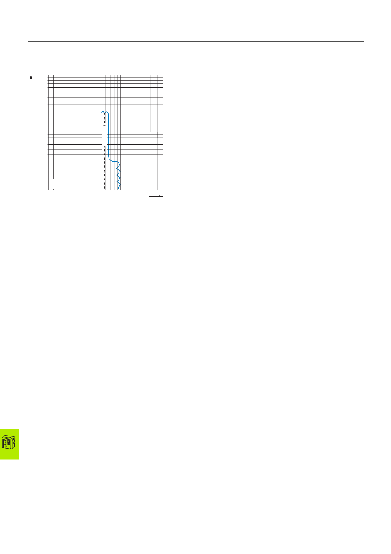
18/24 IZM circuit-breakers, IN switch-disconnectors
Tripping characteristics IZMX16
2010 CA08103002Z-EN
www.eaton.comIZMX16…U... Option Maintenance mode option +IZMX-DTU-ARMS
ARMS-maintenance mode
See Notes 2, 6, 11, 17, 18, 19, 20.
A Set values for overload protection I
r
B Maximum total opening delay
C Minimum total opening delay
D Set value for long delay t
r
E Set value non-delayed short-circuit protection I
i
F Set values for short-time delayed short-circuit protection with flat
characteristic curve
G The end of the characteristic curve is determined by the type of application
and the switching capacity of the selected switch.
H The characteristic curve for the overload release can extend up
to the M1 set value.
I
Available set values for non-delayed short-circuit protection I
sd
J Short-circuit release for very high currents
K Set values for short-time delay at I²t characteristic curve
L Set values for ground-fault protection
M Set values for ground-fault protection delay at
flat characteristic curve
N Flat characteristic curve for the delay time fault protection
O I
2
t characteristic for ground-fault protection delay time
1 The trip unit has a thermal memory, which can shorten the value in the
overload range. This function plays a role whenever a current is higher
than the overload release’s value and which is then isolated by a down-
stream circuit-breaker or the circuit-breaker itself. On a subsequent over-
load current the circuit-breaker will trip more quickly than normal. The
reduced value is inversely proportional to the time expired since the last
overload. After about five minutes the thermal memory is reset.
11 The listed overall switch-off times are conservative and take into account
the trip unit’s maximum response times, the circuit-breaker’s maximum
opening delays and the longest current interruption times with regard to
factors that contribute to worst-case conditions, such as maximum rated
operational voltage, single-phase interruptions and minimum power
factor. Fast breaking times are possible but depend on the system
conditions and the circuit-breaker model.
2 The end of the characteristic curve is determined by the type of
application and the switching capacity of the selected switch.
12 The ground-fault release is activated at a response value of
conventionally 100 % with a tolerance of ±10 %.
3 The overload release trips at 110 % I
r
with a tolerance of ±10 %
(indicated by the “Unit Status” LED). The short-time delayed short-circuit
release I
sd
is activated at a pick-up time of conventionally 100 % with
a tolerance of ±10 %.
13 Unless otherwise specified, the current value tolerances are ±10 % of the
values shown in the diagram.
4 When zone selectivity (ZSI) is activated in the short-time delayed short-
circuit release and no blocking signal is applied, the minimum time value
(0.10 s) applies irrespective of the short-time delay settings.
14 In combination with ARMS function, ground-fault protection is limited to
1200 A.
5 The upper lines of the I
2
t characteristic curves are horizontal from a value
of 8 × I
r
(indicated by the points).
15 When zone selectivity (ZSI) is activated in ground-fault protection and no
blocking signal is applied, the minimum time value (flat characteristic
curve) applies irrespective of the settings.
6 The listed overall switch-off times include the response times of the trip
unit, the opening times of the switch and the time required to switch off
the current.
16 The upper lines of the I
2
t characteristic curves are horizontal from a value
of 0.625 × I
r
(indicated by the points).
7 The characteristic curves apply to applications in a temperature range
from -20 °C to +55 °C. Temperatures over +85 °C cause automatic tripping,
indicated by an orange-colored LED. The circuit-breaker must be selected
according to the temperature-dependent derating values from the table in
the technical data.
17 The maintenance mode function (ARMS) must be activated with a switch
or through the communications terminals for these characteristic curves
to apply. A blue LED indicates that the maintenance mode settings are
active.
8 The non-delayed short-circuit release is activated at a response value of
conventionally 100 % with a tolerance of ±10 %.
18 The shown switch-off times apply for connection to an additional auxiliary
power supply.
9 The non-delayed short-circuit release can be disabled by the user with an
additional Off position.
19 Tripping by the ARMS Maintenance Mode Trip is indicated by the
non-delayed short-circuit protection LED.
10 All trip units feature an additional, permanently set non-delayed short-
circuit release, which becomes active at a peak value of 90 kA. Tripping
by this short-circuit release is indicated by a flashing INST LED. This
protective function remains active when non-delayed tripping is set to Off.
20 The tolerance is ±15 %.
1230DIA-101 (5722B22)
2 3 4 5 6 7 8 910
20
50 40 30
0.5 0.7 0.9
0.6 0.8 1
kA
t
[s]
0.01
0.02
0.03
0.04
0.05
0.06
0.07
0.08
0.09
0.1
0.2
0.3
0.4
0.5
0.6
0.7
0.8
0.9
1
4800A
g
15