


 272 / 543

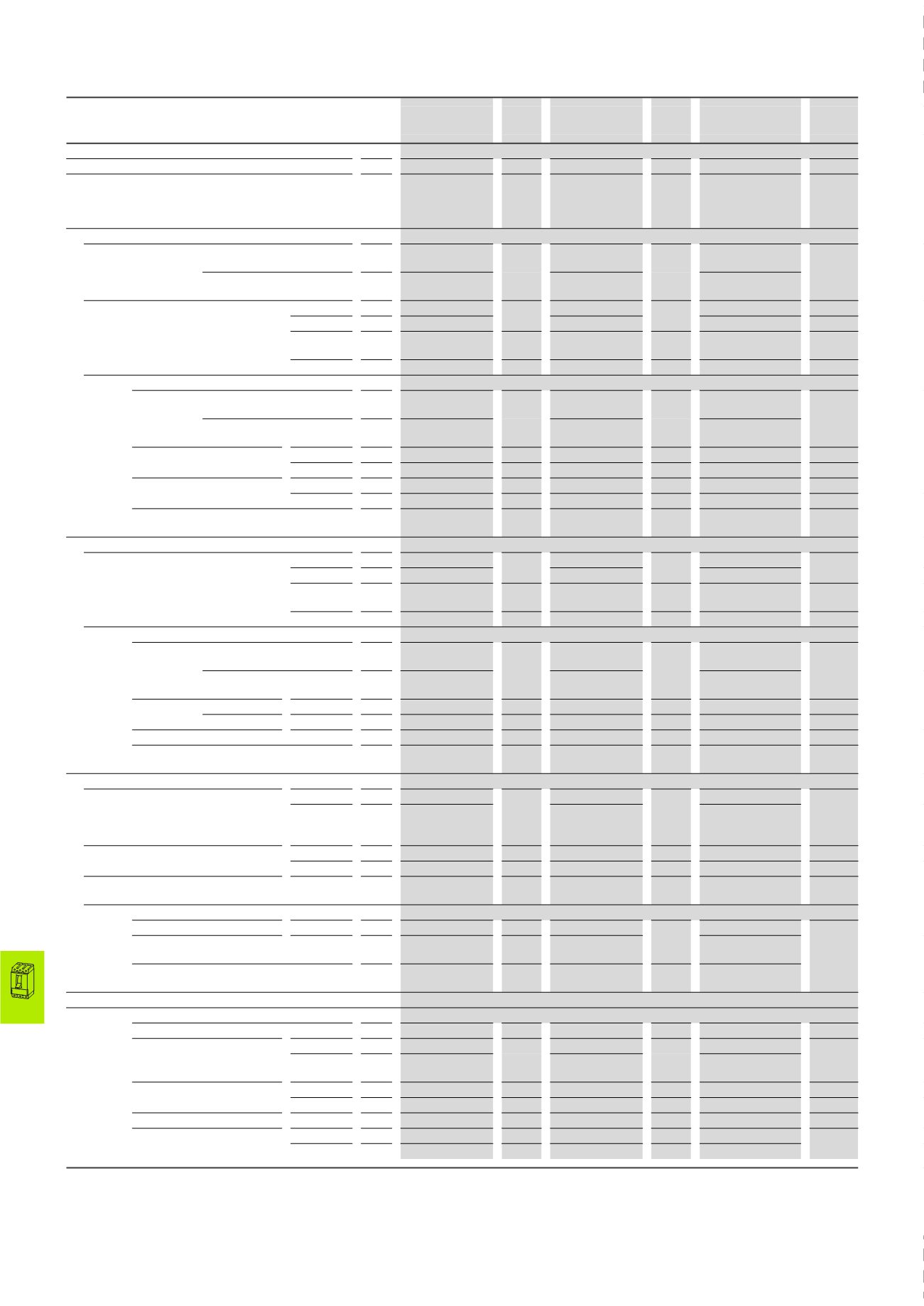
17/176 Circuit-breakers, switch-disconnectors
Terminal capacities
2010 CA08103002Z-EN
www.eaton.comNZM1, PN1, N1,
NS1 160 A
I
n
1)
A
NZM2, PN2, N2,
NS2 300 A
I
n
1)
A
NZM3, PN3, N3, NS3
630 A
I
n
1)
A
Terminal capacities
Standard equipment
Box terminal
–
Screw terminal
–
Screw terminal
–
Accessories
Screw terminals
Tunnel terminals
Rear terminal bolts
Box terminal
Tunnel terminals
Rear terminal bolts
Box terminal
Tunnel terminals
Rear terminal bolts
Copper conductors and cables
Box terminal
Solid
mm
2
1 x (10 – 16)
2 x (6 – 16)
160
1 x (10 – 16)
2 x (4 – 16)
300
2 x 16
500
Stranded
mm
2
1 x (25 – 70)
3)
2 x (6 – 25)
1 x (25 – 185)
2 x (25 – 70)
1 x (35 – 240)
2 x (25 – 120)
Tunnel terminal
Solid
Stranded
mm
2
1 x 16
160
1 x 16
300
–
–
1-hole
mm
2
1 x (25 – 95)
1 x (25 – 185)
1 x (25 – 185)
350
Double-hole mm
2
–
–
–
–
1 x (50 – 240)
2 x (50 – 240)
630
2 x 185
4-hole
mm
2
–
–
–
–
–
–
Screw terminals and connection on rear
Directly on
switch
Solid
mm
2
1 x (10 – 16)
2 x (6 – 16)
160
1 x (10 – 16)
2 x (4 – 16)
300
1 x 16
2 x 16
630
2 x 185
Stranded
mm
2
1 x (25 – 70)
3)
2 x 25
1 x (25 – 185)
2 x (25 – 70)
1 x (25 – 240)
2 x (25 – 240)
Module plate 1-hole
min.
mm
2
–
–
–
–
–
–
max.
mm
2
–
–
–
–
–
–
Module plate 2-hole
min.
mm
2
–
–
–
–
–
–
max.
mm
2
–
–
–
–
–
–
Connection width extension
mm
2
2 x 300
630
2 x 185
Aluminium conductors and cables
Tunnel terminal
Solid
Stranded
mm
2
1 x 16
160
1 x 16
250
1 x 16
350
1-hole
mm
2
1 x (25 – 95)
1 x (25 – 185)
1 x (25 – 185)
2)
Double-hole mm
2
–
–
–
–
1 x (50 – 240)
2 x (50 – 240)
630
4-hole
mm
2
–
–
–
–
–
–
Screw terminals and connection on rear
Directly on
switch
Solid
mm
2
1 x (10 – 16)
2 x (10 – 16)
160
1 x (10 – 16)
2 x (10 – 16)
250
1 x 16
2 x (10 – 16)
400
Stranded
mm
2
1 x (25 – 35)
2 x (25 – 35)
1 x (25 – 50)
2 x (25 – 50)
1 x (25 – 120)
2 x (25 – 120)
Module plate 1-hole
min.
mm
2
–
–
–
–
–
–
1-hole
max.
mm
2
–
–
–
–
–
–
Module plate 2-hole
mm
2
–
–
–
–
–
–
Connection width extension
mm
2
Copper strip (number of segments x width x segment thickness)
Box terminal
min.
mm 2 x 9 x 0.8
160
2 x 9 x 0.8
300
6 x 16 x 0.8
630
max.
mm 9 x 9 x 0.8
10 x 16 x 0.8
(2 x) 8 x15.5 x 0.8
10 x 24 x 1.0
+ 5 x 24 x 1.0
(2 x) 8 x 24 x 1.0
Single flat cable terminal
min.
mm –
–
–
–
–
–
max.
mm –
–
–
–
–
–
Module plate
1-hole
mm –
–
–
–
–
–
Screw terminals and connection on rear
Copper strip, perforated
min.
mm –
–
2 x 16 x 0.8
300
6 x 16 x 0.8
630
Copper strip, perforated
max.
mm –
–
10 x 24 x 0.8
10 x 32 x 1.0
+ 5 x 32 x 1.0
Connection width extension
mm
2
–
–
–
–
(2 x) 10 x 50 x 1.0
Copper bar (width x thickness)
Screw terminals and connection on rear
Screw terminals
M6
–
M8
–
M10
–
Directly on switch
min.
mm 12 x 5
160
16 x 5
300
20 x 5
630
max.
mm 16 x 5
24 x 8
30 x 10
+30 x 5
Module plate 1-hole
min.
mm –
–
–
–
–
–
max.
mm –
–
–
–
–
–
Module plate 2-hole
mm –
–
–
–
–
–
Connection width extension
min.
mm –
–
–
–
–
630
10 x 40
max.
mm –
–
–
–
2 x (10 x 50)
Notes
1)
The rated currents I
n
have been determined according to IEC/EN 60947
(switchgear standard) and generally relate to the max. defined cross-sections. They are given for general reference here.
The engineering standards which apply in each case must be observed.
2)
To 240 mm
2
can be connected depending on the make of cable.
3)
To 95 mm
2
can be connected depending on the make of cable.
NZM…, PN…, NS…, N…