


 332 / 336

Cam switches, switch-disconnectors
Switch-disconnectors
2010 CA08103002Z-EN
www.eaton.com4/107
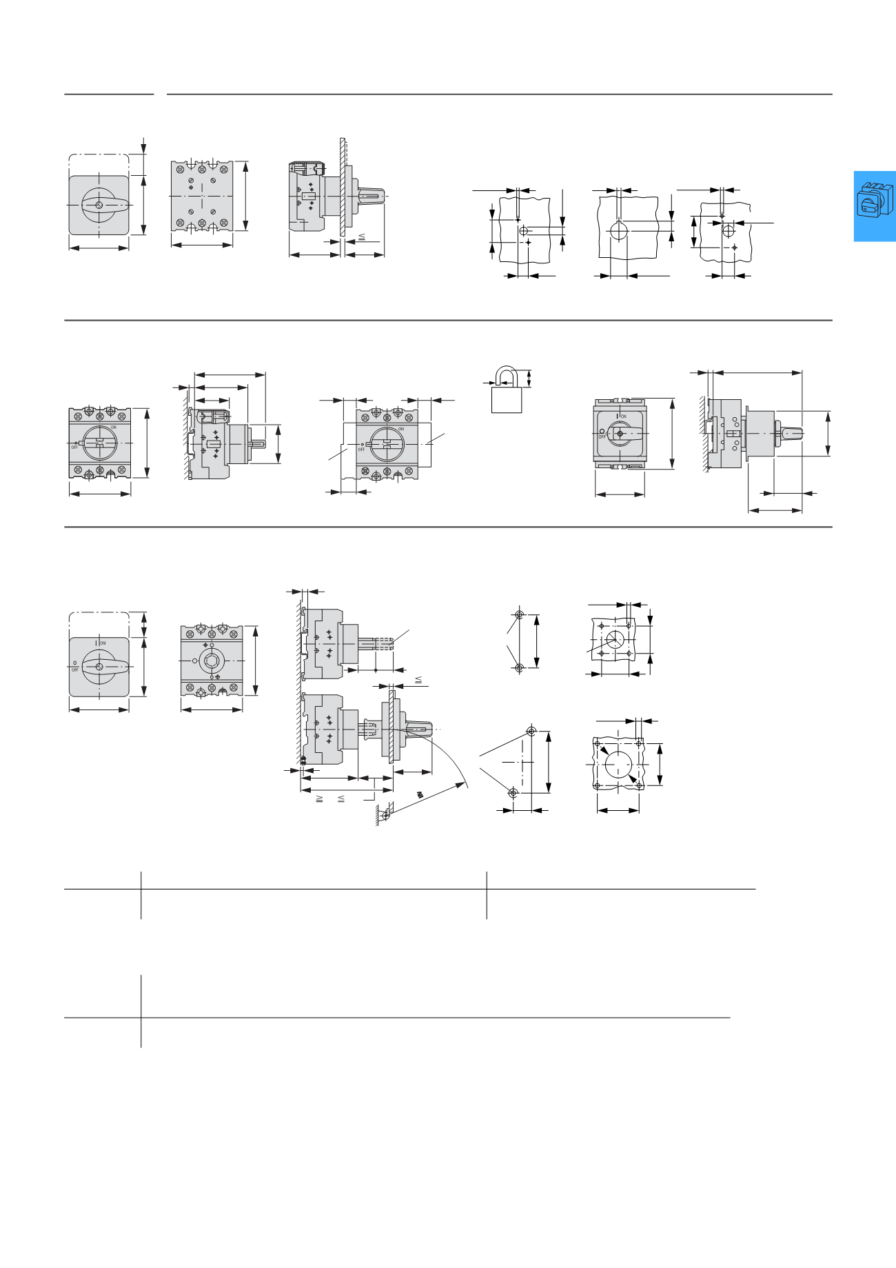
Flush mounting
P.../E
Center mounting
P1.../EZ
Drilling dimensions
door
P1-.../E
P1-.../EZ
P3-.../E
Service distribution board flush mounting
P3.../IVS
≦ 3 padlocks
P1.../IVS
Rear mounting
P.../Z
① Shaft extension with ZAV-... possible ≦ 4 x 25 = 100 mm
Drilling dimensions
base
P1.../Z
P3.../Z
Drilling
dimensions
door
ON
0
I
OFF
a2
b2
b22
b3
a3
L3
L1
T3
T1
L2
T2
1
2
3
4
5
6
5
c2
c21
P1.../EZ = c2 + 5 mm
4.1 – 4.5
3.2
22.3
+0.4
0
12.5
10 – 11
12.2
3.1 – 3.5
30
14
37
12 – 13
b3
a4
c22
c23
c3
5
45
N
HI11
L3
L2
L1
T3
T2
T1
L3
L2
L1
T3
T2
T1
a32
a32
a31
d
b
d = 4 – 8 mm
b + d
F
47 mm
49
L1 L2 L3
T1 T2 T3
55
28
b3
45
5
c3
a
38,
3
5
a3
5
b22
b2
a2
c21
c25
c20
R
100
c31 c32
b3
54
5 – 5.5
M4
65
36
36
22.3
+0.4
0
M4
75
25
5 – 5.5
48
48
30.5
Part no.
a2
a3
a4
a21 a22 a23 a31 a32 a33 b2
b3
b21 b22 b23 b24 b31
P1
P3
48
87
49
72
53.5
71.5
65
87
48
87
87
125
15
18
15
15
83
114
48
87
70
83
65
87
17
27
180
175
32
–
49
60
Part no.
c2
c3
c20
≧/≦
c20 with
≦ 4
ZAV/ZVV
c21 c22 c23 c24 c25 c27 c28 c31 c32 c33
P1
P3
59
59
86
82
96 – 112
103 – 118
212
218
35
37
32
41
65
63
68
81
58
65
35
44
77
90
25
25
25
25
27
29
P1, P3