SPECIFICATION:
1.
POWER: 220V to 240V ~ 50Hz.
2.
Fuse: T6.3A, 250VAC.
3.
Time adjustment from 10sec to 20min.
4.
Lux adjustment: ‘Light level’ sensing from 2 Lux to 1000 Lux.
5.
Range of detection from 2m to 12m radius. Detection range can be
adjusted using the supplied shroud stickers
6.
Switching capacity: 1000W incandescent light / 500VA fluorescent
light / 500VA Energy saving lamp.
7. 6001/6002
detection range: please refer to the fig.2.
8.
Auto mode / Test mode / Timer mode.
9.
Operating temperature: -10ºC to +40ºC.
10.
Storage temperature: -25ºC to +70ºC.
11.
Terminal capacity: 2 x 1.5mm
2
.
WIRING:
Warning:
Products should be installed by a qualified electrician. Ensure
that the sensor is screwed securely to the ceiling without any movement.
1.
The phase (L) and neutral (N) conductors of the supply cable are
connected according to terminal assignment.
2.
The output (or load) phase (L’) and neutral (N) connectors are to be
connected to the load terminals marked L’ and N.
6001/6002
CEILING & CORRIDOR MOUNT
INDOOR MOTION SENSOR
l
SPECIFICATION:
1.
POWER: 220V to 240V ~ 50Hz.
2.
Detection range: refer to fig. 1.
3.
Time adjustment: 30 sec, 1min, 3min, 5min, 10min, 20min, 30min
(
apply to Master sensor only)
4.
Lux adjustment: ‘Light level’ sensing from 5 to 1000 Lux. (apply to
Master Sensor only)
5.
Sensitivity adjustment: 0.5m to 4m radius.
6.
Switching capacity: 1800W incandescent light / 1100VA fluorescent
light / 1100VA Energy saving lamp
7.
Master sensor can be connected to up to 5 slave sensors.
8.
Warm up: 60 sec.
9.
Test mode: Lux adjustment switch to maximum. Light turns on for 3
sec in each trigger.
10.
Short time pulse mode: Time adjustment switch to minimum. 1 sec
ON, 9 sec OFF.
11.
Operating temperature: -10ºC to +40ºC.
12.
Storage temperature: -25ºC to +70ºC.
13.
Terminal capacity: 2 x 1.5mm
2
.
WIRING:
Warning:
Products should be installed by a qualified electrician. Ensure
that the sensor is fixed securely to the ceiling without any movement.
1.
The phase (L) and neutral (N) conductors of the supply cable are
connected according to terminal assignment.
2.
The OUTPUT phase (L’) and neutral (N) conductors are to be connected
to the load terminals marked L’ and N.
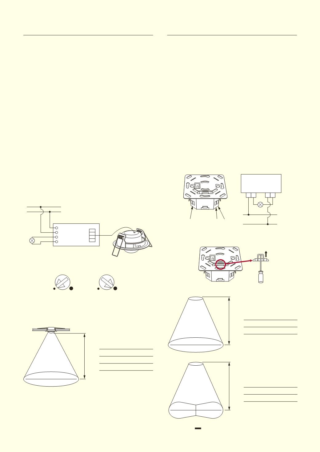
CEILING FLUSH-MOUNT MASTER & SLAVE
OCCUPANCY SENSOR 6004 & 6005
l
INSTALLATION:
1.
Fuse can be replaced by using a screwdriver to pull up the fuse.
N N L L’
6001 / 6002
N
L
N
N
L L’
N
L L’
N
N
L L’
N
L
N
L’
L
N
6001
HEIGHT
RADIUS (M)
2.3
10
2.5
11
3.0
12
6002
HEIGHT
RADIUS (M)
2.5
11
3.0
12
Ø 24m
360
º
3
m
High
3
m
High
12
m
12
m
360
º
3
m
3
m
NOTE: 6002 detection range is achieved by aligning the double
arrow along corridor.
t
t
S
S
HEIGHT
RADIUS (M)
2.3
3.5
2.4
4
3.0
5.5
Ø 8m
360
º
2.4
m
High
Minimum
Maximum
FIG. 1
FIG. 2


