


 171 / 211

TECHN I CAL DATA
COMMUN I CAT I ONS
171
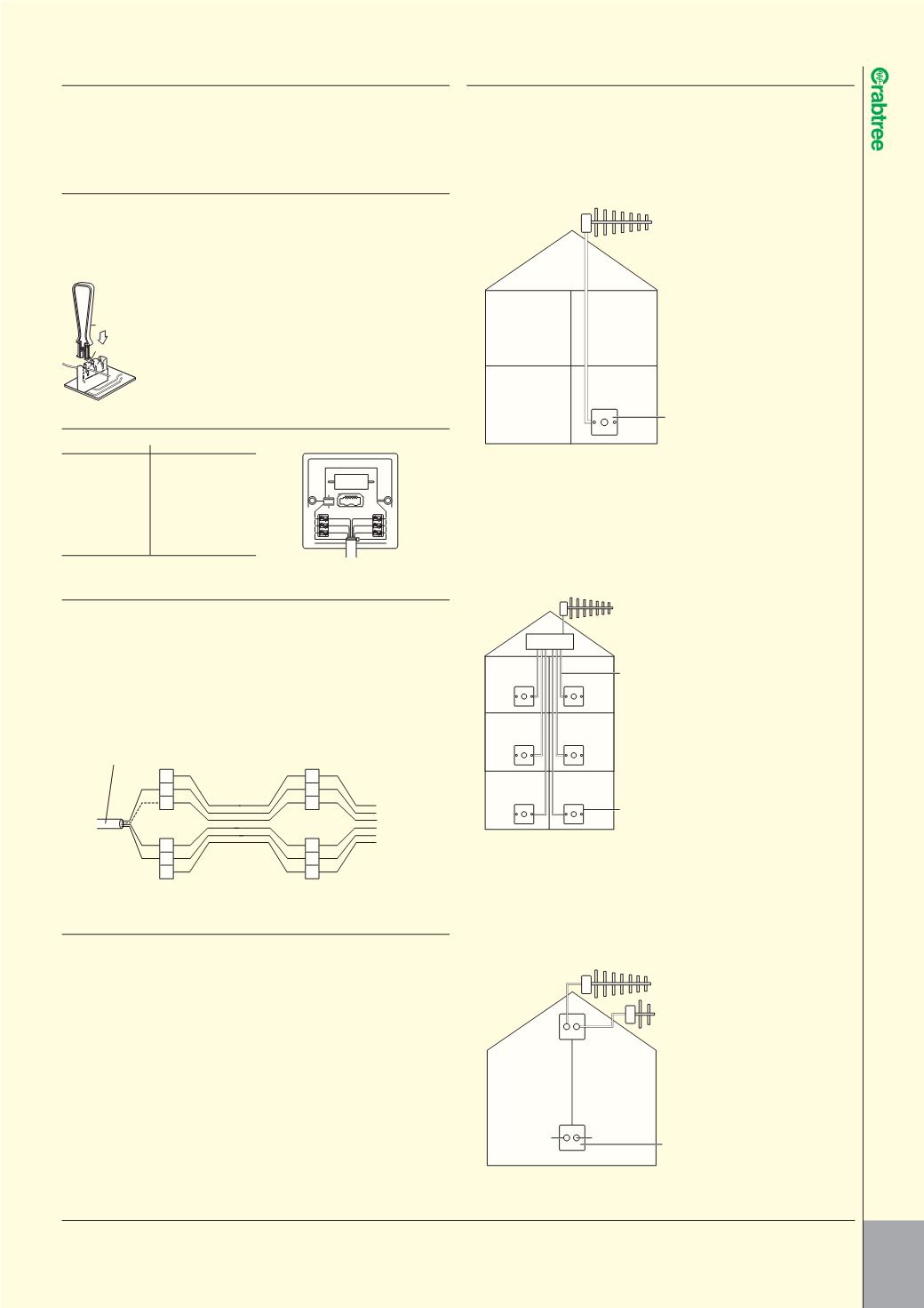
CO-AXIAL SOCKET OUTLETS
l
In order to comply with the latest EMC directives, all
installations containing amplification systems or
comprising multiple co-axial socket outlets must be
fitted with appropriate earth bonding.
Isolated Co-Axial Sockets are isolated 2kV.
Separate co-axial cable
down lead to each
outlet
7267 – Single Isolated
connection outlet
TV
Amplifier
TV
FM
Loft
outlet
FM
aerial
lead
TV aerial
lead
Co-axial
down lead
To TV
Living room outlet
To radio
7268 – Twin
connection
outlet
CAPITAL TELEPHONE SOCKET OUTLETS
l
The Crabtree Capital range of Telephone Socket Outlets
has been developed primarily for use in telephone systems
using British Telecom standards. The products are similar
in specification to units available from British Telecom.
TERMINATIONS
l
All telephone outlets should be wired in accordance with the wiring diagrams
shown below. Connection of these telephone outlets is by the IDC (Insulation
Displacement Connection) method allowing one or two equal size cables
(0.40–0.68mm) to be terminated per connection block, using Crabtree
connection tool List No.6915 as shown below.
Allow 50mm cable ‘tails’ at each connection block
Push home in direction of arrow with connection tool
Excess cable may be trimmed using wire cutters
WIRING COLOUR CODE
l
Pin number
Base colour/stripe
1
Green/White
2
Blue/White
3
Orange/White
4
White/Orange
5
White/Blue
6
White/Green
WIRING DIAGRAMS
l
Example of typical connections:
1
Connections to 2 & 5
2
Earth recall (when used) connect to terminal 4
3
Connection to terminal 3 is not usually required
NB
(a) Standard 4 wire cable is shown below as incoming cable. If terminals
1 and 6 (normally unused) are required, 6 wire cable may be used.
NB
(b) All socket outlet connections are in parallel – any number of socket
outlets can be connected, but it is recommended that only a
maximum of 5 telephones be used at any one time on one line.
WARNING NOTES
l
In order to comply with current Wiring Regulations, metal faceplate telephone
socket outlets must be within the ‘equipotential zone’ of the building they are
located in. Therefore an earth terminal is fitted to metal plate units which should
be connected to the electrical installation’s earthing system.
Testing
(a) Connect cables as shown in wiring diagram
(b) Plug in telephones
(c) Lift receivers and check for dial tone
(d) Make an incoming call to check bells work
(e) If circuit does not work, disconnect and check thoroughly before reconnecting
Note
Unauthorised connection of telephone socket outlets to wiring owned by British
Telecom is an offence. Further information concerning the requirements of a
telephone system installation can be obtained from the Department of Industry
or the telephone equipment supplier.
Connection tool
Connection block
1
2
3
6
5
4
3
2
1
3
2
1
6
5
4
6
5
4
Existing incoming cable from PBX, etc
1st socket outlet
(Single master)
Additional socket outlet(s)
(Single secondary)
7265 – Single Direct
connection outlet
TV
TV/FM outlet installation
Co-axial outlet installation
Communal aerial system eg flats, hotels etc
Single connection outlet
Domestic installation
Note
If additional outlets are
required, an amplifier
should be used. Each
outlet is then wired
separately to the
amplifier.
TV and FM aerial
connections use a twin
connection outlet
(7268) and one
co-axial down lead.
1 Fit a co-axial
connector to the TV
and FM aerial cables.
2 Plug connectors into
7268 in loft.
3 Connect a co-axial
cable run between
back of 7268 in loft
and back of 7268 in
the living room, then
plug TV and FM radio
into front of plate.
As seen from rear