


 10 / 211

CAP I TAL
CONT ROL
10
4521/31
4520/31
4523/3
4506
4506
4507
rear view
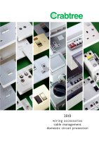
45A DP ‘SLIM LINE’ COOKER CONTROL UNITS
l
BS 4177 & BS 1363
PACK QTY
45A DP main switch and 13A switch socket
1
4521/1
outlet. Faceplate marked ‘cooker’
45A DP main switch and 13A switch socket with 1
4521/31
neon indicators. Faceplate marked ‘cooker’
Dimensions
146mm x 86mm
Mounting boxes
9054 surface, SB625 flush galv. or SB629 dry lining
Same plate size as standard twin socket.
Large capacity tunnel terminals on live and neutral take up to 10mm
2
cable.
Two earth terminals are fitted.
Separate double pole switching for both cooker and socket outlet.
45A DP COOKER CONTROL UNITS
l
BS 4177 & BS 1363
PACK QTY
45A DP main switch and 13A switch socket
1
4520/1
outlet. Faceplate marked ‘cooker’
45A DP main switch and 13A switch socket with 1
4520/31
neon indicators. Faceplate marked ‘cooker’
Dimensions
168mm x 114mm
Mounting boxes
9052 surface or 9338/GV flush
50A DP COOKER CONTROL UNITS
l
PACK QTY
Faceplate marked ‘cooker’
1
4523
Faceplate marked ‘cooker’
1
4523/3
and fitted with neon indicator
Blank Faceplate
1
4211/BLANK
Dimensions
165mm x 178mm
Mounting boxes
For ‘retro fit’ applications – allows use of original flush box
Durable white powder coated metal faceplate.
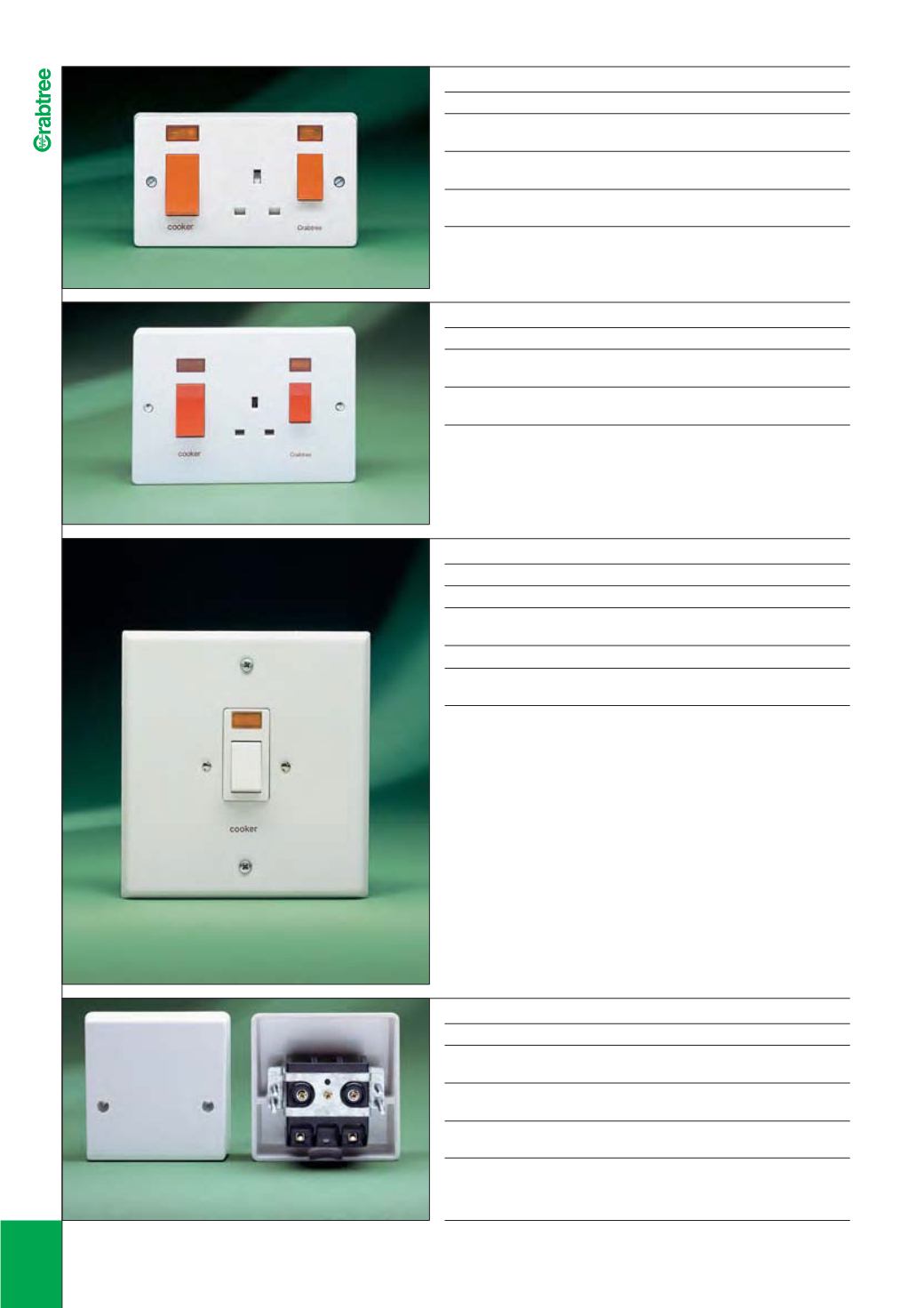
45A CABLE OUTLETS
l
BS 5733
PACK QTY
With terminals and cable clamp
10
4506
Terminals will accept 2 x 10mm
2
cable
With cable clamp
10
4507
Cable clamp will accept 1 x 16mm
2
through cable
Dimensions
86mm x 86mm
Mounting boxes
9041 surface, SB615 flush galv. or SB632 dry lining
Cable knock-out in cover prevents access to terminals before outgoing cable is fitted.