
8/22
Total Solution to Earthing & Lightning Protection |
9AKK106354A3360
8
Earth bar accessories
Length
Width
Height
Weight each
Part no.
Description
(mm)
(mm)
(mm)
(kg)
Copper earth bar
LK004
Swan-neck link
400
50
36
0.42
LK205
Disconnecting link 125
90
77
0.59
Tinned copper earth bar
LK004-T
Swan-neck link
400
50
36
0.42
LK205-T
Disconnecting link 125
90
77
0.59
– Fix using countersunk wood screws 1
1
⁄
2
” No. 12 (Part no. SW110) and wall plugs (Part no. PS310) fixings only apply to
disconnecting link
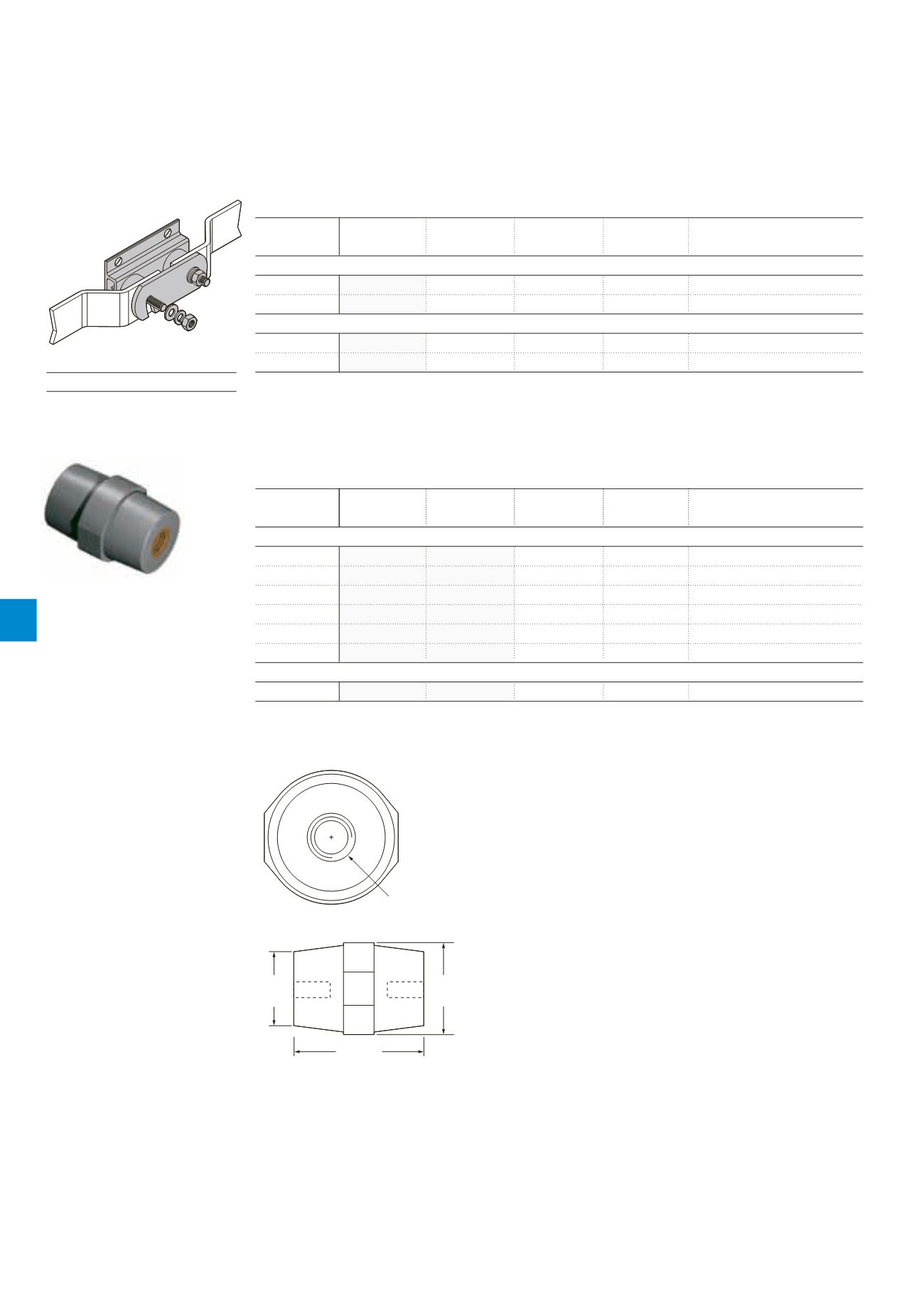
Insulator
Height (A)
Top diameter (B) Max diameter (C) Insert
For copper bar size
Part no.
(mm)
(mm)
(mm)
size
(mm)
Insulator
IN020
20
Ø 14
Ø 18
M6
25 x 3
IN030
30
Ø 25
Ø 33
M6
25 x 6
IN040
40
Ø 31
Ø 39
M8
38 x 6
IN013
50
Ø 27
Ø 35
M10
50 x 6
IN060
60
Ø 38
Ø 52
M10
75 x 6
IN070
70
Ø 51
Ø 55
M12
100 x 6
Insulator with 2 studs and 3 nuts
IN005
50
Ø 27
Ø 35
M10
50 x 6
– Insulator manufactured from grey GRP material with brass insert
Top
diameter
(B)
Max.
diameter
(C)
Height (A)
Insert size (D)
Top
diameter
(B)
Max.
diameter
(C)
Height (A)
Insert size (D)
Earth bonds & clamps
Accessories
Standards
BS 7430


