


 170 / 248


559E4100.indd
Connection
DB115711
a
(+)
2
4 à 415
V
a
(-)
S
D1
S
D4
S
D
2
S
D3
S
TD
or output 1
P
A
L Ir
or
S
DG
or output
2
SD
x
Q
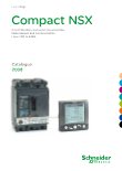
Wiring diagrams
Compact NSX100 to 630
SDx module with Micrologic
Symbols
SD1, SD3:
SDx-module power supply
SD2:
output 1 (80 mAmax.)
SD4:
output 2 (80 mAmax.)
SD2
SD4
Micrologic 2
SDT
-
Micrologic 5
SDT or output 1 PAL Ir or output 2
Micrologic 6
SDT or output 1 SDG or output 2
Terminals shown in red
O
must be connected by the customer.
Operation
DB115712
Circuit bre
ak
er
trip order
Circuit bre
ak
er
reset
P
A
L Ir
S
DG
S
DT
Q
> 90 % Ir
I
> 105 % Ir
tr
a
t
6
Ir
I:
charge current
PAL Ir:
thermal overload pre-alarm
SDG:
ground-fault signal
SDT:
thermal-fault signal
Q:
circuit breaker
The diagram is shown with circuits de-
energised, all devices open, connected and
charged and relays in normal position.
D-8
version: 1.0