


 48 / 124

48
PB104477-35
DB118804
DB118805
Electrical auxiliaries
for iC60, iID, iDPN Vigi, iSW-NA,
RCA and ARA (cont.)
Protection
Circuit protection
Earth leakage protection
PB104478-35
PB104480-35
*(Ua)
Voltages measured between the phase and the neutral conductor, at which the iMSU device must control the associated protective device.
Tripping
Auxiliaries
iMN
iMNs
iMNx
Type
Undervoltage release
Instantaneous
Delayed
Independent of the supply voltage
Function
b
b
Trips the device with which it is combined when its input voltage decreases
(between 70 % and 35 % Un). Prevents device closing again until its input voltage is
restored
b
b
Tripping of the associated device by
opening of the control circuit
(e.g. push-button, dry contact)
b
b
Not tripping on transient voltage dip
(up to 0.2 s)
b
b
A drop in the supply voltage does not
trip the associated device
b
b
A locking push-button control allows
the circuit protected (e.g. machine
control) to be placed in safety
configuration
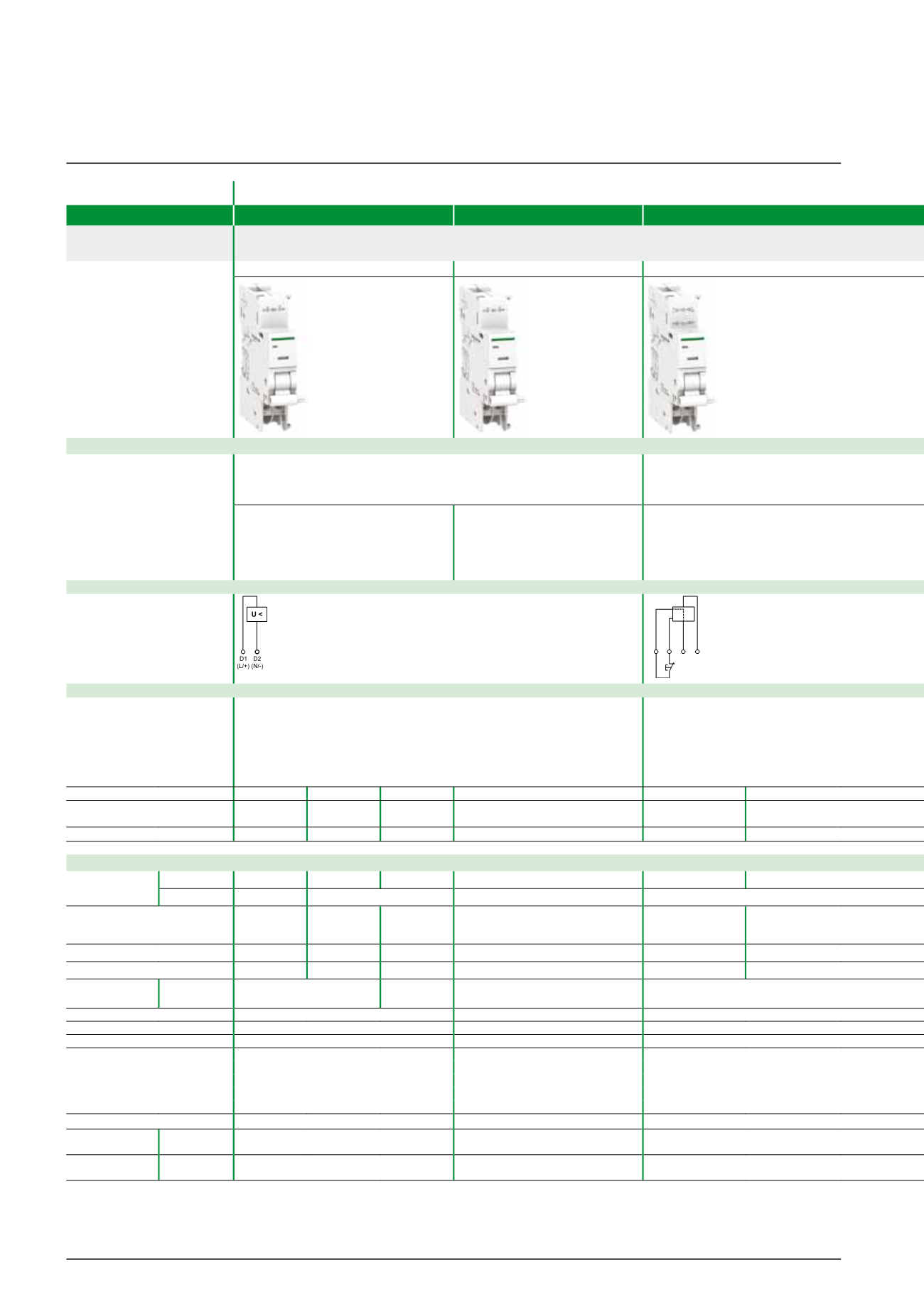
Wiring diagrams
U <
E2 N/
L1
L2
E1
Use
b
b
Emergency stoppage by normally closed push button
b
b
Ensures the safety of power supply circuits for several machines by preventing
"uncontrolled" restarting
b
b
Emergency stoppage with fail-safe
principle
b
b
Insensitive to control circuit voltage
variation to increase service continuity
Important: Before any servicing
operation switch off the mains power
supply (voltage presence at terminals
E1/E2)
Catalogue numbers
A9A26960 A9A26961 A9A26959 A9A26963
A9A26969
A9A26971
iC60, iID, iDPN Vigi, iSW-NA, RCA
et ARA
b
b
b
b
b
b
b
b
b
b
b
b
iC60, iID double terminals
b
b
b
b
b
b
b
b
b
b
b
b
Technical specifications
Rated voltage
(Ue)
V AC
220…240 48
115
220…240
220…240
380…415
V DC
–
48
–
–
Standardised operating and
non-response to voltage times
(Ua)*
–
–
–
–
–
–
Maximum operating time
–
–
–
–
–
–
Minimum non-response time
–
–
–
–
–
–
Operating
frequency
Hz
50/60
400
50/60
50/60
Red mechanical indicator
On front face
On front face
On front face
Test function
–
–
–
Width in 9 mm modules
2
2
2
Operating current
–
–
–
Number of contacts
–
–
–
Operating
temperature
°C
-35…+70
-35…+70
-35…+70
Storage
temperature
°C
-40…+85
-40…+85
-40…+85