Basic HTML Version


8/103
● The enclosure monitor checks and protects all the equipment in the distribution,
network and server racks as well as their environment.
● Ambient parameters and operating states can be measured using various sensors
and several inputs.
● Signalling and display: on the unit, serial interface, Ethernet network.
● Digital inputs and switching outputs enable permanent monitoring and adapted
actions.
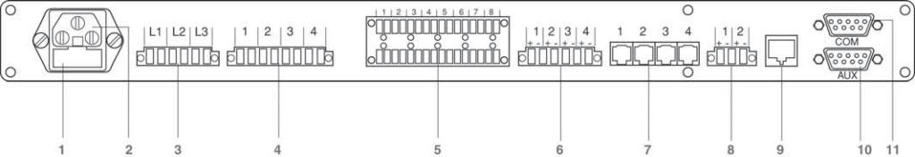
Connections and cabling diagram
1
Contact pin circuit breaker.
2
Connection to the network.
3
Connection of phase surveillance.
4
Digital switching outputs.
5
Digital inputs (ref.
NSY11955
and
NSY11958
).
6
Alarm inputs (ref.
NSY11954
and
NSY11956
).
7
Connection of a sensor, references
NSY11951
,
NSY11952
and
NSY11953
.
8
Connection of uninterruptible power supply.
9
Connection to Ethernet network RJ45.
10
Series interface for external devices.
11
Series interface for connection to a terminal.
Reference
NSY11950
Possibilities for connection to the enclosure monitor:
– 4 sensors ref.
NSY11951
,
NSY11952
and/or
NSY11953
.
– 4 sensors ref.
NSY11954
or
NSY11956
.
– 8 insulated digital inputs (free potential).
– 2 digital inputs.
– 1 series input used for monitoring devices with a communication protocol.
08_103_106_CC010.indd 103
29/1