


 199 / 244

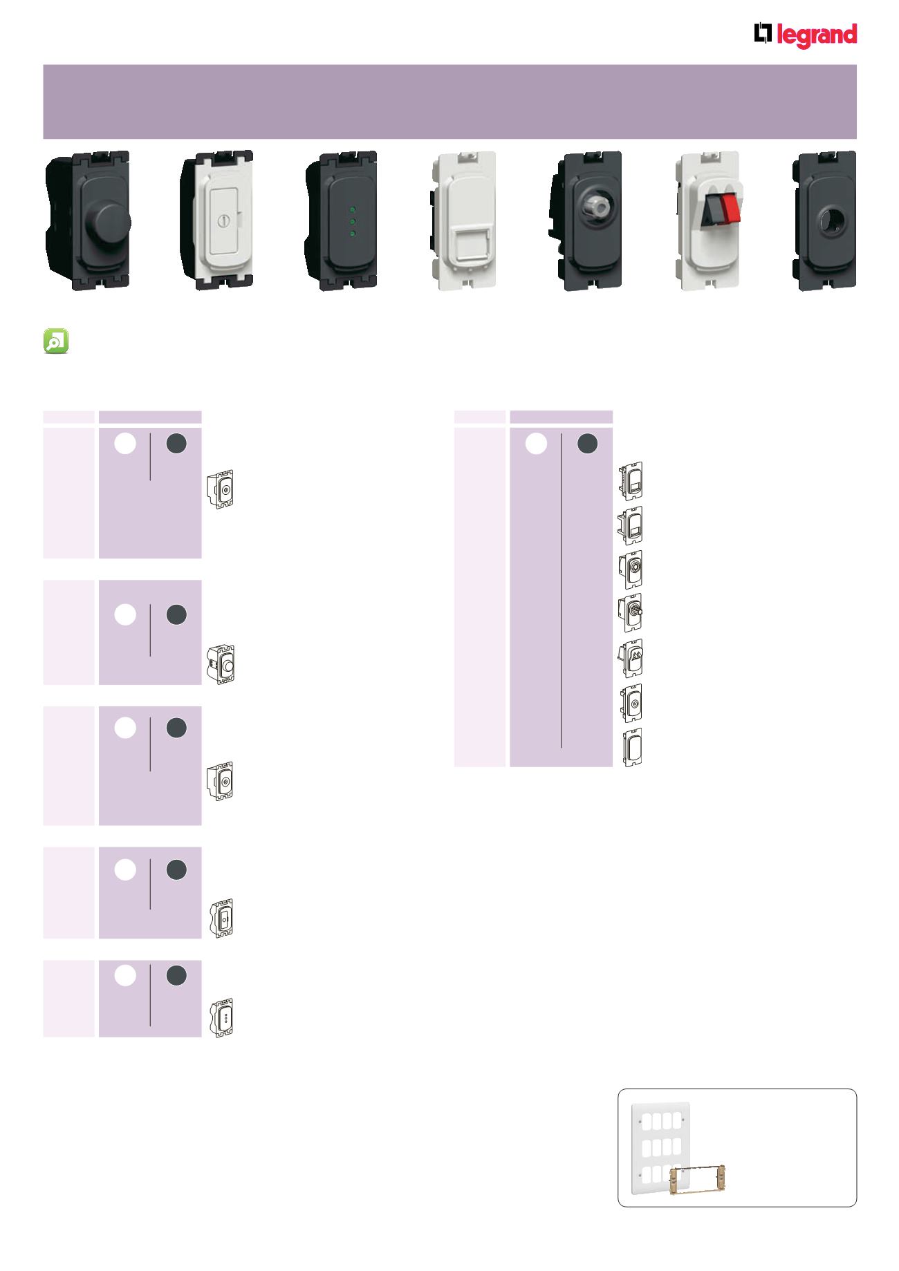
191
Pack
Cat. Nos.
Ancillary modules
White
Anthracite
1
7354 50 7355 50
Telephone socket - single master
1
7354 51 7355 51
Telephone socket - single secondary
10
7352 56
7353 56
RJ 45 data outlet CAT 6 compliant
Rapid cable connection
UTP 8 contact
10
7354 40 7355 40
Screened TV - single
Non-isolated male Ø9 . 5 mm
10
7354 41 7355 41
Screened satellite
10
7352 65 7353 65
Hi-fi outlet - screw terminal
1
7354 35 7355 35
Cable outlet
20
7354 36 7355 36
Blank module
7355 48
7351 62
7352 56
7355 41
7350 30
7352 65
Synergy
®
grid system
dimmer, fuse carrier and ancillary modules
Modules mount from front into grid yokes
Individually removable without disturbing grid
Pack
Cat. Nos.
Dimmer unit modules
100 - 240 V
±
50/60 Hz
White
Anthracite
Conform to BS EN 60669-2-1
1
7354 46 7355 46
Dimmer for use with tungsten filament
lamps, good quality wire-wound
transformers and compatible
electronic transformers for low
voltage loads
1
40 - 300 W
Not suitable for fluorescent loads
Fuse carrier modules
13 A - 250 V
±
White
Anthracite
Conform to BS 5733
10
7350 30
7351 30
Fuse module fitted with
BS 1362 13 A fuse
White
Anthracite
Indicator modules - 250 V
±
Conform to BS 5733
1
7350 60
7351 60
Indicator - red LEDs
1
7350 62
7351 62
Indicator - green LEDs
Time delay switch
100 - 240 V
±
50/60 Hz
White
Anthracite
Conform to BS EN 60669-2-3
1
7354 47 7355 47
Multiple way soft start time delay switch
Push operated delay pre-set for 3, 10
or 30 minutes
40 - 400 W
Not suitable for fluorescent loads
Dimmer unit modules -
dimmable HF ballast fluorescent
100 - 240 V
±
50/60 Hz
White
Anthracite
Conform to BS EN 60669-2-1
1
7354 48 7355 48
1 way leading edge dimmer for
dimmable HF ballast fluorescent
0-10 V 400 W
1 : Can be used in conjunction with compatible electronic
transformers for low voltage loads. It will be necessary to
test that the dimmer mechanism is compatible with the
electronic transformer identified for installation
7355 35
Complete range of grid front plates and yokes p. 194-195 Installation options p. 193 Grid selection charts p. 194-195