
lighting management
BUS/KNX system
touch screen control and interface
lighting management
BUS/KNX system
installation supervision
■
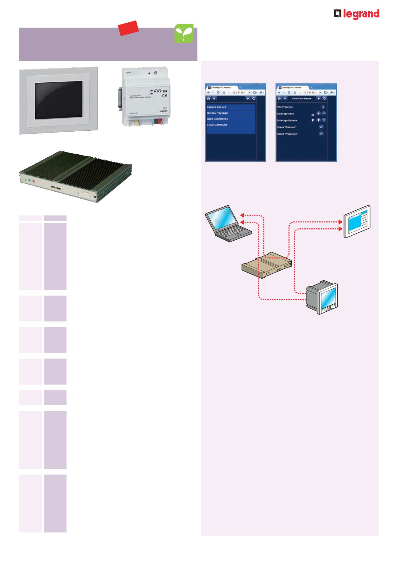
Operating principle of the IP communication
module Cat. No. 0035 43
■
Operating principle of the supervision
gateway Cat. No. 0035 44
LAN
Cat. No. 0488 84
Measurement control unit
0035 43
0035 44
Pack
Cat. Nos.
5 . 7'' touch screen control - scenario
management
1
0488 84 BUS/KNX multiple scenarios
For connection to BUS/KNX cable Cat. No. 0492 91
(below) with the connectors installed on the product
Allows several BUS/KNX controllers to be operated
Allows manual or programmed control of lighting
(lighting level), openings, fans and multimedia
equipment
Manages scenario programming (for example : time
management, lighting, presence)
Supplied complete with aluminium finishing plate,
support and flush mounting box
BUS/KNX - USB interface
1
0035 47 Used to connect a PC to the BUS/KNX system via
the USB port
1 x 17. 5 mm DIN module
KNX/BUS coupling unit
1
0035 16 For extending the installation beyond 64 KNX units
To use with Cat. No. 0035 12
2 modules
Modular power supply unit
1
0035 12 230 V
±
29 V
=
- 320 mA
4 modules
BUS/KNX cable
1
0492 91 Length 500 m
IP communication module
1
0035 43 BUS/KNX - IP gateway
2 functions :
- The IP interface provides the link between the
BUS/KNX infrastructure and the IP network to set the
parameters remotely with ETS tool
- Web communication interface to activate scenarios
remotely via a dedicated web page
Enables off-site operation
4 x 17. 5 mm DIN modules
Building manager
1
0035 44 Used together with Legrand and third party systems,
this building manager enables :
- Processing and combination of the data from these
systems (KNX, Modbus and Bacnet protocols)
- Automatic control by time programming, load
shedding, management of conditions, etc.
- Alarm monitoring and surveillance
- All these data to be available for an overall
supervision system
0488 84
NEW
97


