


 56 / 582

BETA Protecting
Miniature Circuit Breakers
Additional components
1/34
Siemens ET B1 · 10/2008
1
*
You can order this quantity or a multiple thereof.
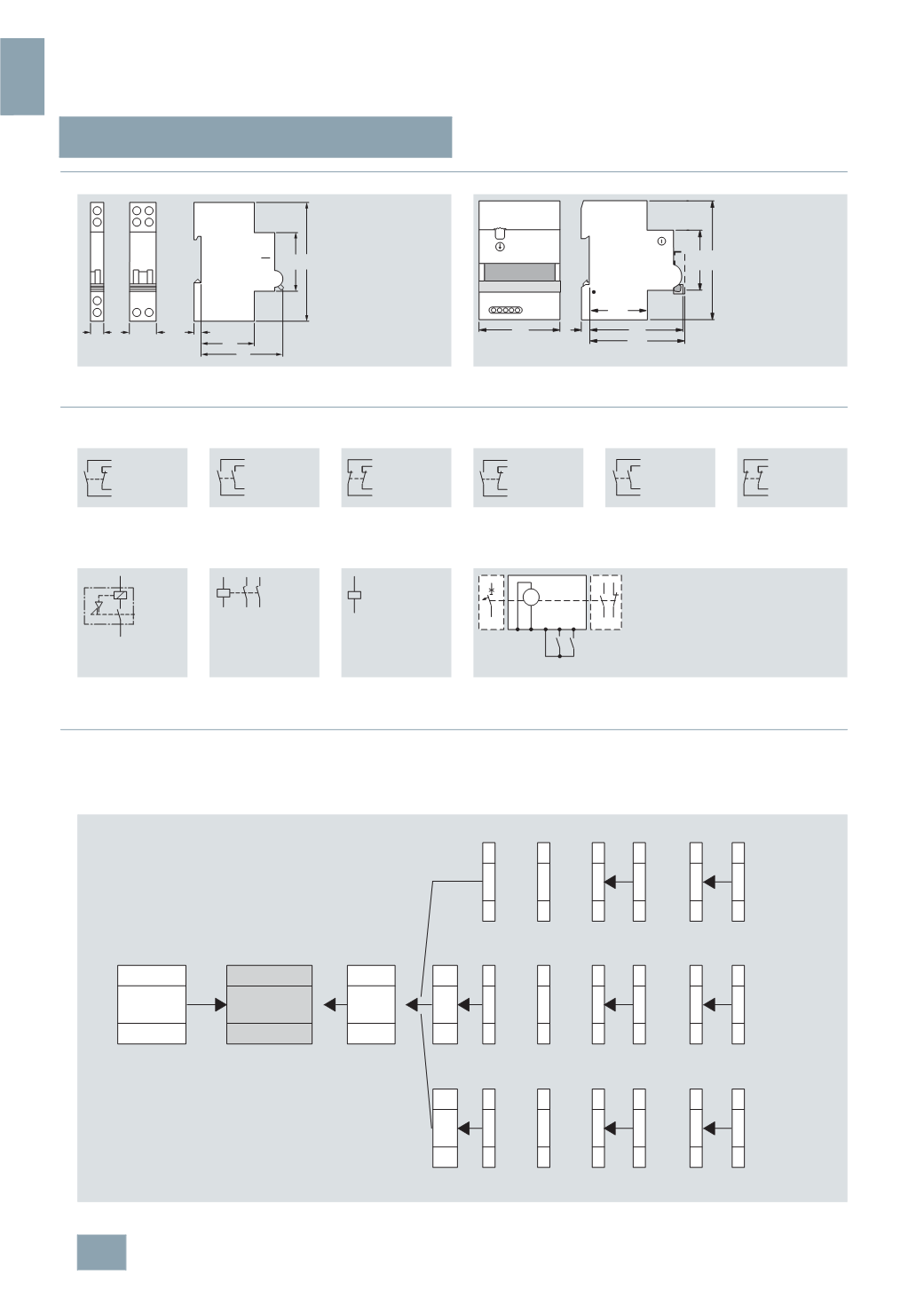
■
Dimensional drawings
■
Schematics
■
More information
Using this mounting concept, all additional 5ST3 components
can be combined with miniature circuit breakers of the 5SY and
5
SP4 series (no RC unit on 5SY5 universal current MCB).
The 5SY6 0.. miniature circuit breakers are only designed for the
mounting of auxiliary switches, fault signal contacts and remote
controlled mechanisms. The chart shows which additional
components can be mounted on either the right or the left.
AS
FC
UR
ST
RC
Auxiliary switches (AS)
Fault signal contacts (FC)
5
ST3 010
5
ST3 013
5
ST3 011
5
ST3 014
5
ST3 012
5
ST3 015
5
ST3 020
5
ST3 021
5
ST3 022
Shunt trips (ST)
Undervoltage releases (UR)
Remote controlled mechanisms (RC)
5
ST3 030
5
ST3 031
5
ST3 040
5
ST3 041
5
ST3 042
5
ST3 043
5
ST3 044
5
ST3 045
5
ST3 050
I2_13657
45
90
44
70
6
18
9
90
45
I2_12624
74
73
6
44
63
M
I2_10741a
P N 1 2 3
ON OFF
I2_13658a
or
or
or
or
or
or
or
5
ST3
MCB
RC
RC unit
AS
FC
AS
FC
AS
FC
AS
FC
FC
AS
AS
FC
AS
FC
AS
FC
AS
FC
FC
AS
AS
FC
AS
FC
AS
FC
AS
FC
FC
AS
ST
UR
or
or
5
SM2
5
SY / 5SP4
MCB:
Miniature circuit breaker
RC:
Remote controlled mechanism
UR:
Undervoltage release
ST:
Shunt trip
AS:
Auxiliary switch
FC:
Fault signal contact
© Siemens AG 2008