Basic HTML Version


3/133
04653
04662
B
A
C
A
A
A
Busbar configuration
The bars are supported by insulating supports: 3 fixed
supports (screwed to the framework) are compulsory.
If necessary, use additional mobile supports.
The bars rest against one of the fixed supports by
means of a wedge screwed onto each bar.
The table on this page shows:
• The number and section of the bars to be used
according to the permissible current level of the
busbar.
• The number of bar supports to be installed
according to the rated short-time withstand
current (Icw en KA eff/15).
• The busbar is installed in suitable enclosures with
width 700 mm and depth 500 mm.
Busbar selection
Flat bars with width 1675 mm
Bar supports
3 fixed supports are compulsory for supporting the vertical busbars. If more than
3 supports are required, use the mobile supports (additional).
Bar wedging
A metal wedge with thickness 5 mm is screwed onto the bar.
It rests against a fixed support and wedges the bar.
Connection to a horizontal busbar, thickness 10 mm
Fixed bar support
04653.
Mobile bar support
04662.
Wedging: 1 bar/phase.
Wedging: 2 bars/phase.
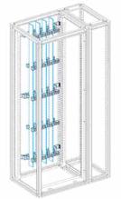
Busbar with Icw 40 kA eff/1 s.
The bars are supported by 3 fixed supports,
04653 (compulsory), and 2 mobile supports,
04662
.
B = max. 100 mm
A = max. 375 mm
C = max. 87.5 mm
Number of copper bars and supports
system
Rear busbars up to 1600 A
Flat bars, thickness 10mm
Permissible current
level (A) for panel
No. of bars/phase
and section (mm)
No. of supports according to the rated
short-time withstand currents Icw (kA eff/1 s)
IP 31
25 30 40 50 60 65 75 85
1080
1 bar, 50 10
1250
1 bar, 60 10 3
5
7
9
1600
1 bar, 80 10
Note: The busbar permissible current level values are provided for an ambient temperature of 35 °C around
the panel.
Perforated copper bar
Reference
50 10 mm
04525
60 10 mm
04526
80 10 mm
04528
Bar support
Reference
fixed for rear flat busbar
04653
mobile (additional)
04662
Wedge for bars
Reference
100 5-mm wedges for bars
04669
Connection
1600 A
Reference
to horizontal bars,thickness
10 mm
L 80 mm
04636 (1) (2)
L 80 mm
04636 (2) + 04642 (1)
(1) A part of the link must be made using insulated flexible bars.
(2) References
04635
and
04636
are delivered as a unit = 1 link per phase.
.
.
.
25
03_121_135_SFM080.indd 133
20/