


 36 / 73

35
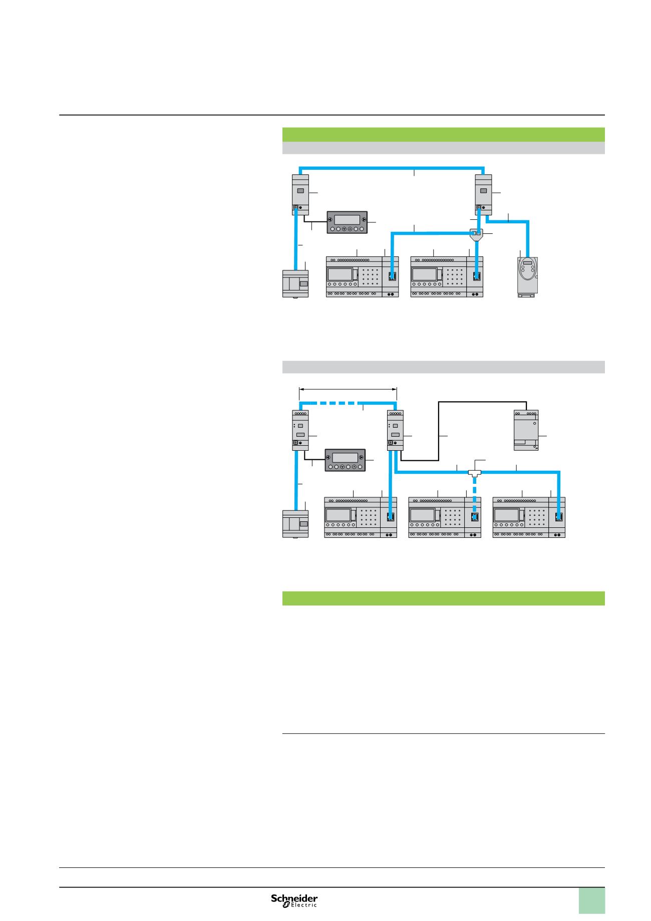
Connection examples
Example 1
6
9
9
8
7
6
6
5 bis
6
5
10
1
10
3
2
4
Total length of cables between Twido and ATV 31:
y
30 m
1
Twido master.
2
Modbus network (cable TWD XCA RJP03)
3
Slave display unit XUBT N401.
4
Connecting cable XBT Z938.
5
Junction box TWD XCAT3RJ
(polarisation and line end adapter activated).
5 bis
Junction box TWD XCAT3RJ (no polarisation
but line end adapter activated).
6
Modbus network (cables VW3 A8 306R
pp
).
7
T-junction VW3 A8 306TF
pp
.
8
ATV 31 variable speed controller.
9
Modbus communication module
SR3 MBU01BD.
10
Modular smart relay SR3 B
ppp
BD.
Example 2
10
3
2
11
1
12
11
12
11
12
6
5
5 bis
9
8
4
7
7
y
1000 m
1
Twido master.
2
Modbus network (cable TWD XCA RJP03)
3
Slave display unit XUBT N401.
4
Connecting cable XBT Z938.
5
Junction box TWD XCA ISO (polarisation and
line end adapter activated).
5 bis
Junction box TWD XCA ISO (no polarisation but
line end adapter activated).
6
Modbus network (cables TSX CSA
p
00).
7
Modbus network (cables VW3 A8 306R
pp
).
8
Supply cable
c
24 V.
9
Regulated power supply from the Phaseo
Modular range.
10
T-junction 170XTS04100.
11
Modbus communication module
SR3 MBU01BD.
12
Modular smart relay SR3 B
ppp
BD.
Function description
The Modbus slave communication module is connected to a 2-wire or 4-wire
Modbus network
(1)
.
The maximum length of the network between the two TWD XCAISO T-junctions is
1000 m (9600 bauds max., AWG 26).
Amaximum of 32 slaves can be connected to the Modbus network, or a maximum
of 247 slaves with repeaters.
Line end adapters must be fitted to both ends of the line (1 nF/10 V, 120
W
/0.25 W
in series).
The line must be polarised (470
W
/0.25 W resistors)
(2)
.
The connection cable and its RJ45 male connectors must be screened.
The
t
terminal on the module must be connected directly to the protective earth
at one point on the bus.
b
b
b
b
b
b
b
(1) Please refer to installation instructions supplied with the product.
(2) The polarisation resistors must be managed by the master.
Characteristics :
page 36
Functions :
page 37
References :
page 42
Dimensions, mounting :
page 43
Description
1
Zelio Logic smart relays
1
Communication
Modbus slave communication protocol
1
2
3
4
5
6
7
8
9
10